
Anti-oscillation apparatus and technique for securing wind turbine blades against oscillations

a technology of oscillation and anti-oscillation apparatus, which is applied in the direction of propellers, sustainable buildings, motors, etc., can solve the problems of wind turbine blade structure damage that is costly and time-consuming to repair, oscillation of edge wise blades, etc., and achieves the effect of easy attachment to the blad

Active Publication Date: 2016-04-19
VESTAS WIND SYST AS
View PDF10 Cites 11 Cited by
  • Summary
  • Abstract
  • Description
  • Claims
  • Application Information

AI Technical Summary

Benefits of technology

The patent text describes a blade cover that can be used to improve the performance of a blade, such as an aircraft blade. The cover can be made from netting, which is a lightweight material that can be easily attached to the blade. The cover also has a non-aerodynamic surface that reduces the amount of air movement around the blade, which can make it more durable and efficient. The cover can be attached to the blade with an adhesive surface, which makes it easy to transport and install. Overall, this invention provides a way to protect and improve the performance of blade components in various industries.

Problems solved by technology

When the blades of the wind turbine are locked and at a stand still, they are prone to edge wise blade oscillations (edge wise is the direction from the leading edge to the trailing edge of the blade) resulting from the air flow across or around the blade, when the wind hits the blade from the side.
If the wind turbine blades can be feathered with respect to the wind, then the wind flows around the blades smoothly, but without power to continuously adjust the blade pitch, the wind direction will inevitably change and result in a situation where the flow around the blade is not smooth.
The worst case is when the incident wind meets the blade perpendicular to one of its flat surfaces and has to flow around the leading and trailing edge of the blade.
If the oscillations are of a large enough magnitude, they can result in physical damage to the structure of the wind blade that is costly and time consuming to repair.
The problem is caused by the largely unstable flow of air around the rotor blade, particularly the leading edge, when the blade is pitched out of the wind.
The air flows around the curved surface of the blade, but cannot stay attached to the blade surface in laminar flow because the blade is not pitched correctly to support lift.
As a result, a laminar air flow may briefly occur but is then lost, resulting in the formation of a vortex in the flow on the leeward side of the blade.
If the rhythmic oscillation provided by the air flow corresponds to the resonance frequency of the blade itself, the blade can eventually suffer a catastrophic failure.
Although, such devices do solve the problem, they can be expensive and difficult to install.

Method used


Image

  • Anti-oscillation apparatus and technique for securing wind turbine blades against oscillations
  • Anti-oscillation apparatus and technique for securing wind turbine blades against oscillations
  • Anti-oscillation apparatus and technique for securing wind turbine blades against oscillations

Examples


Embodiment Construction

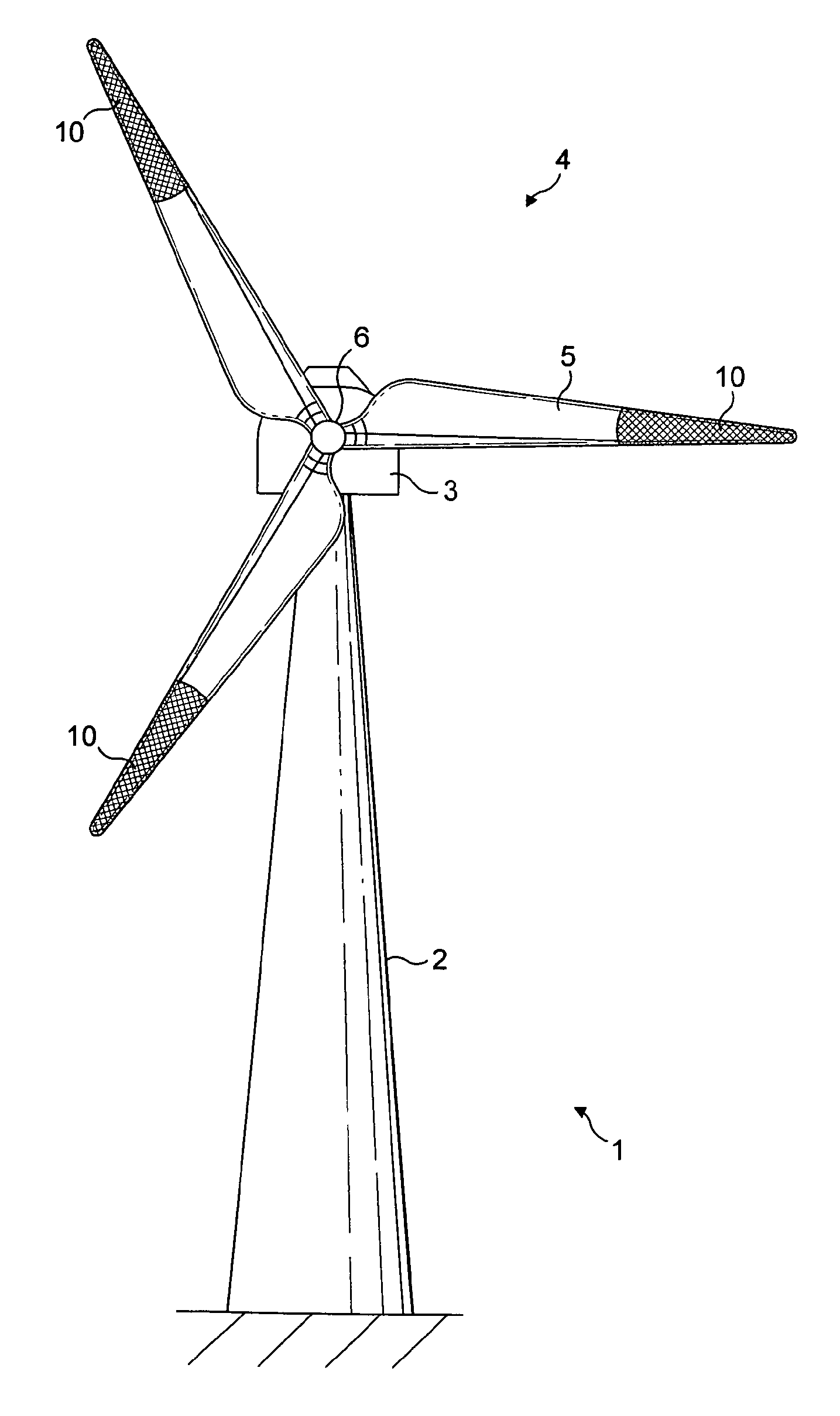
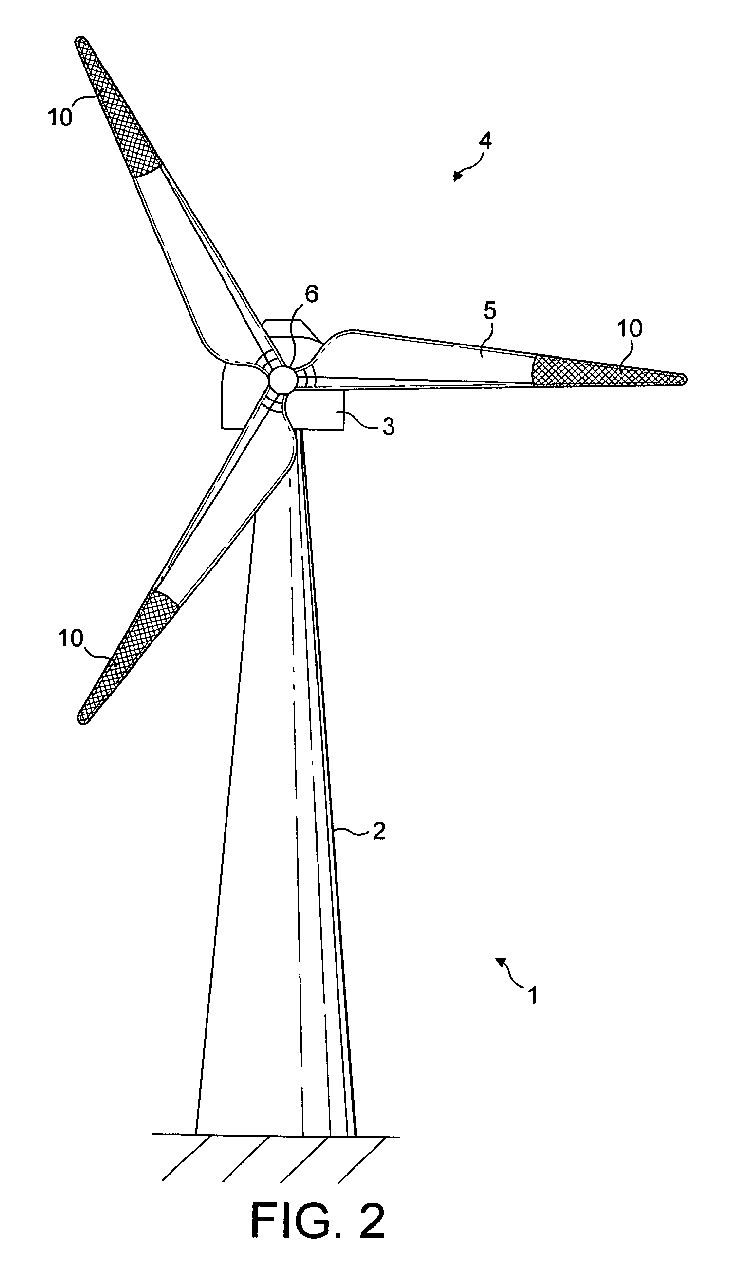
[0026]A first example of the invention will now be described in more detail with reference to FIGS. 2 and 3 of the drawings.

[0027]The example anti-oscillation apparatus comprises a sleeve 10 that is fitted over the tip of a wind turbine blade 5 when the blade is in a stationary position. Attachment of the sleeve 10 can be carried out in situ when the wind turbine blades of an operational wind turbine have been locked in position for maintenance or repair. Alternatively, the sleeve 10 can be attached to the blade 5 in the factory, prior to installation of the blade 5 on the wind turbine tower 2, and before the wind turbine is connected to the grid to output electricity. In both cases, therefore, the wind turbine can be thought of as being in a non-operational mode. Once the sleeve is in place, the blade can be unlocked and can idle in a feathered position, if desired.

[0028]The construction of an example anti-oscillation sleeve 10 is shown in more detail in FIG. 3. The sleeve 10 compr...


PUM


Abstract

The invention relates to a method of operating a wind turbine (1) to guard against oscillations of the wind turbine blades (5) when they are at a standstill or idling at low speeds, and to a wind turbine blade anti-oscillation apparatus (10). The apparatus comprises a releasably attachable blade cover (10) that provides a non-aerodynamic surface for a region of the blade. This has been found to prevent air flow adhering to the blade and periodically detaching in a phenomenon known as vortex shedding, and therefore prevents oscillations of the blade becoming problematic. The blade cover can comprise a sleeve (10) of a net-like material, that can be positioned on the blade either before installation or in the field by service engineers using guide lines 16 and 17.

Description

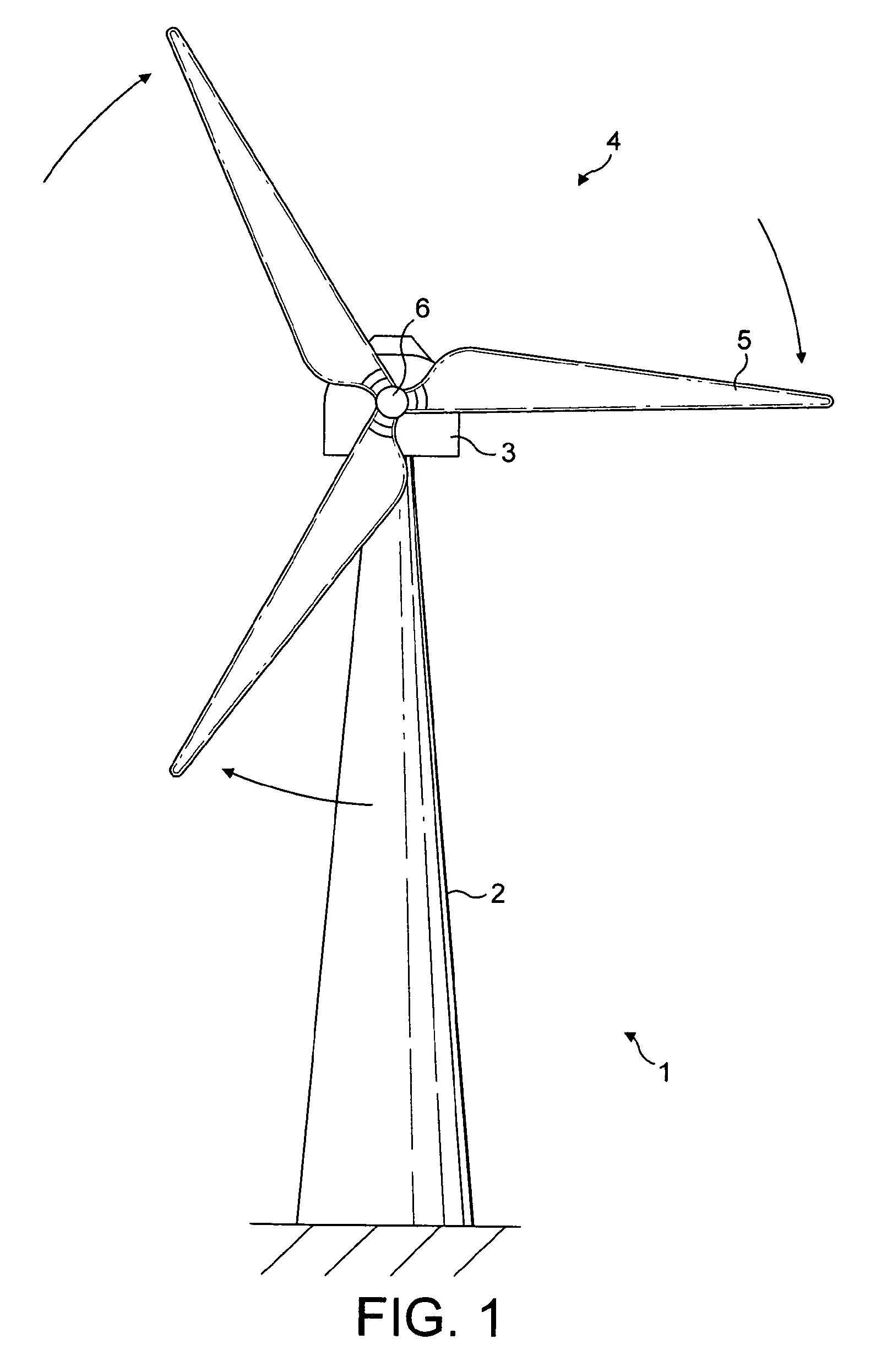
[0001]This invention relates to an anti-oscillation apparatus and to technique for securing wind turbine blades against oscillations.[0002]A typical horizontal axis wind turbine is illustrated in FIG. 1 to which reference should now be made. FIG. 1 illustrates a wind turbine 1, comprising a wind turbine tower 2 on which a wind turbine nacelle 3 is mounted. A wind turbine rotor 4 comprising at least one wind turbine blade 5 is mounted on a rotor hub 6.[0003]The hub 6 is connected to the nacelle 3 through a shaft (not shown) extending from the nacelle front. The nacelle 3 can be turned, using a yaw drive positioned at the top of the tower 1, to change the direction in which the rotor blade hub 6 and the blades 5 are facing. The blades are aerodynamically profiled so that they experience a ‘lift’ or pressure from the wind as the wind flows past the surface of the blade. The angle or pitch at which the leading surface of the blade aerodynamic profile meets the incident wind can be alter...

Claims


Application Information

Patent Timeline
Patent Type & Authority Patents(United States)
IPC IPC(8): F03D1/00
CPCF03D1/001F03D1/003F03D11/00Y02B10/30Y02E10/722Y02E10/728F03D13/10F03D80/00F03D80/50Y02E10/72
Inventor BECH, ANTON
Owner VESTAS WIND SYST AS
Learn More