Power storage device
a power storage device and power storage technology, applied in the direction of electrochemical generators, cell components, batteries, etc., can solve the problems of difficulty in obtaining the theoretical capacity as high as the discharge capacity, and achieve the effect of improving the discharge capacity or charge capacity improving the performance of the power storage device, and increasing the rate at which a reaction substance is occluded or released by/from the silicon layer
- Summary
- Abstract
- Description
- Claims
- Application Information
AI Technical Summary
Benefits of technology
Problems solved by technology
Method used
Image
Examples
embodiment 1
[0033]In this embodiment, an electrode of a power storage device which is an embodiment of the present invention and a manufacturing method thereof will be described.
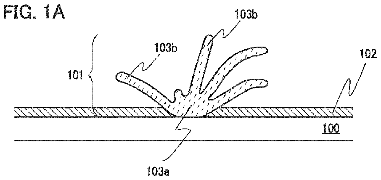
[0034]The electrode of the power storage device and the manufacturing method thereof will be described with reference to FIGS. 1A to 1C.
[0035]As illustrated in FIG. 1A, a silicon layer is formed as an active material layer 101 over a current collector 100 by a thermal CVD method, preferably, an LPCVD method. Thus, an electrode including the current collector 100 and the active material layer 101 is formed.
[0036]The current collector 100 serves as a current collector of the electrode. Thus, a conductive material having a foil shape, a plate shape, or a net shape is used. The current collector 100 can be formed using, but not particularly limited to, a metal element with high conductivity typified by titanium, platinum, aluminum, copper, or the like. Note that in the case of using aluminum for the current collector, an al...
embodiment 2
[0062]In this embodiment, a power storage device according to an embodiment of the present invention will be described.
[0063]The power storage device according to an embodiment of the present invention includes at least a positive electrode, a negative electrode, a separator, and an electrolyte. The electrode described in Embodiment 1 is used as the negative electrode.
[0064]The electrolyte is a nonaqueous solution containing a salt or a solution containing a salt. Any salt can be used as the salt as long as it contains carrier ions such as alkali metal ions, alkaline earth metal ions, beryllium ions, or magnesium ions. Examples of the alkali metal ions include lithium ions, sodium ions, and potassium ions. Examples of the alkaline earth metal ions include calcium ions, strontium ions, and barium ions. In this embodiment, a salt containing lithium ions (hereinafter referred to as a lithium-containing salt) is used as the salt.
[0065]With the above structure, a lithium-ion secondary ba...
embodiment 3
[0092]The power storage device according to an embodiment of the present invention can be used as a power supply of various electric devices which are driven by electric power.
[0093]Specific examples of the electric device utilizing the power storage device according to an embodiment of the present invention are as follows: display devices, lighting devices, desktop personal computers and laptop personal computers, image reproduction devices which reproduce still images and moving images stored in recording media such as digital versatile discs (DVDs), mobile phones, portable game machines, portable information terminals, e-book readers, cameras such as video cameras and digital still cameras, high-frequency heating devices such as microwave ovens, electric rice cookers, electric washing machines, air-conditioning systems such as air conditioners, electric refrigerators, electric freezers, electric refrigerator-freezers, freezers for preserving DNA, and medical electrical equipment ...
PUM
| Property | Measurement | Unit |
|---|---|---|
| width | aaaaa | aaaaa |
| length | aaaaa | aaaaa |
| temperature | aaaaa | aaaaa |
Abstract
Description
Claims
Application Information
 - R&D
- Intellectual Property
- Life Sciences
- Materials
- Tech Scout
- Unparalleled Data Quality
- Higher Quality Content
- 60% Fewer Hallucinations
Browse by: Latest US Patents, China's latest patents, Technical Efficacy Thesaurus, Application Domain, Technology Topic, Popular Technical Reports.
© 2025 PatSnap. All rights reserved.Legal|Privacy policy|Modern Slavery Act Transparency Statement|Sitemap|About US| Contact US: help@patsnap.com


