Apparatus and method for pre-baking substrate upstream of process chamber

a technology of apparatus and substrate, which is applied in the direction of lighting and heating apparatus, drying machines, furnaces, etc., can solve the problems of requiring a longer time to raise and control the temperature, and the efficiency of heating in the reduced pressure is not as good as in the atmospheric pressure, so as to improve the wafer run rate and shorten the heating up period , the effect of efficient heating

Active Publication Date: 2016-05-24
ASM IP HLDG BV
View PDF22 Cites 332 Cited by
  • Summary
  • Abstract
  • Description
  • Claims
  • Application Information

AI Technical Summary

Benefits of technology

[0007]The mainstay of semiconductor automation is shuttling products (e.g., silicon wafers or quartz photo-masks) between ultra-clean storage carriers and a variety of process tools (e.g., processing, measurement, or testing chambers) through an equipment front end module (EFEM). In some embodiments to solve at least one of the above-discussed problems, pre-baking is conducted substantially at an atmospheric pressure in an EFEM area, not in a process chamber. In some embodiments, a pre-baking station is provided in a mini environment in the EFEM area. In some embodiments, the pre-baking station has a BOLTS interface (Box Opener / Loader-to-Tool Standard Interface; mechanical interface), not at a wafer cooling stage location, so that the pre-baking station can be installed universally in all tools. Alternatively, the pre-baking station can be installed at a wafer cooling stage location by replacing a cooling station with the pre-baking station if the system need not have a cooling stage. In some embodiments, in order to increase the wafer run rate, a heating up period is made short by providing multi-stage heating slots in the pre-baking station, wherein multiple wafers stored in respective slots are heated simultaneously. In some embodiments, also in order to efficiently heat wafers so as to shorten a time to heat up wafers and accelerate degassing, hot nitrogen injection ports are provided in the pre-baking station to blow hot nitrogen gas along wafers stored in the pre-baking station. In some embodiments, a wafer is sandwiched or inserted between heating media (e.g., heated aluminum plates) so that the wafer is heated from both top and bottom, thereby shortening a heating up period as compared with heating equipment of general multi-slot-type ovens.

Problems solved by technology

Further, since the process chamber is controlled at a low pressure, and thermal conductivity and transfer are low under a reduced pressure, heating in the reduced pressure is not as efficient as in atmospheric pressure, requiring a longer time to raise and control the temperature.

Method used


Image

  • Apparatus and method for pre-baking substrate upstream of process chamber
  • Apparatus and method for pre-baking substrate upstream of process chamber
  • Apparatus and method for pre-baking substrate upstream of process chamber

Examples


example 1

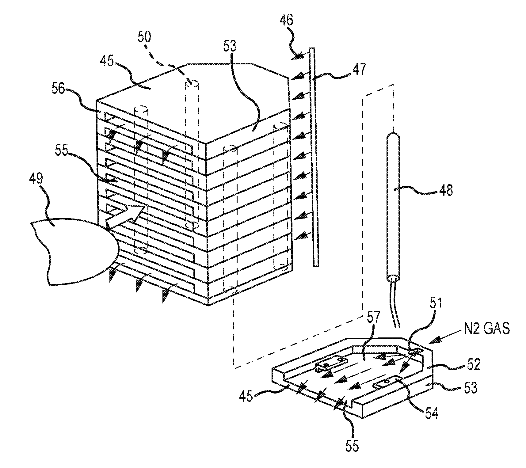
[0054]Temperature distributions inside a pre-baking station illustrated in FIGS. 2A to 2C, 4, and 5, attached to a minienvironment illustrated in FIG. 3, were evaluated. FIG. 7 is a schematic plan view of a compartment showing temperature-measurement positions on a substrate (a 300-mm wafer). A first cartridge heater 77a was installed in each side wall near the slit 76 (front opening), a second cartridge heater 77b (having a higher heat capacity than the first cartridge heater) was installed in each side wall behind the first cartridge heater 77a, and a third cartridge heater 77c (having the same heat capacity as the first cartridge heater) was installed in the rear wall next to a N2 gas buffer pipe 75 on both sides. The set temperature of the cartridge heaters was 100° C. A heated nitrogen gas (the temperature was set at 100° C. at a N2 heat exchanger) was introduced into the compartment from the center of the rear wall through a square nozzle at 30 SLM. A thermocouple (TC) 74 was ...

example 2

[0056]A run rate (throughput: the number of wafers processed per hour), RR, was estimated using a system substantially similar to that used in Example 1 by simulation. The conditions for the simulation were as follows:

[0057]Loading pattern: Cascade (from one FOUP, loading a wafer to a front end robot (FE RB; an atmospheric robot), loading a wafer to a load lock chamber, loading a wafer to a back end robot (BE RB; a vacuum robot), loading a wafer to each of multiple reaction chambers are conducted simultaneously, for processing);

[0058]The number of slots of the pre-baking station: 12;

[0059]The duration of pre-baking at the pre-baking station: 200 seconds;

[0060]Platform: Pentagonal WHC with four process modules each having two reactors (single-wafer batch processing) and two load lock chambers;

[0061]Pre-baking operation: Three conditions (no pre-baking; pre-baking in a reaction chamber; pre-baking in an EFEM); and

[0062]Thickness of film deposited: Two conditions (100 Å; 320 Å).

[0063]T...


PUM


Abstract

A pre-baking apparatus for heating a substrate upstream of a process tool is adapted to be connected to an EFEM (equipment front end module) and includes: a chamber which has a front face with multiple slots arranged in a height direction of the chamber, and which is divided into multiple compartments extending from the multiple slots, respectively, toward a rear end of the chamber for loading and unloading substrates; and a connecting frame for connecting the chamber to the process tool. The multiple compartments are separated from each other by a divider plate and provided with heaters for heating the multiple compartments, and each compartment has a gas injection port for blowing a hot inert gas over the substrate placed therein toward the slot.

Description

BACKGROUND OF THE INVENTION[0001]1. Field of the Invention[0002]The present invention generally relates to an apparatus and method for pre-baking a substrate such as a semiconductor wafer upstream of a process chamber, wherein the pre-baking is conducted to remove moisture from a film such as a resist film before processing the film.[0003]2. Description of the Related Art[0004]In order to bake out moisture, etc. from a film (such as a film including a resist film), after loading a wafer to a process chamber, the film is pre-baked and degassed before processing the wafer in the process chamber. Since the process chamber is used for the pre-baking and degassing process, regardless of the type of the process chamber (a single-wafer reactor or batch reactor), a wafer run rate or throughput is decreased due to the time used for pre-baking and degassing in the process chamber. Further, since the process chamber is controlled at a low pressure, and thermal conductivity and transfer are low...

Claims


Application Information

Patent Timeline
Patent Type & Authority Patents(United States)
IPC IPC(8): F26B11/00H01L21/67H01L21/677F27B9/12
CPCH01L21/67109H01L21/67775H01L21/67778F27B2009/124F27B17/0025
Inventor KAMATA, KEISUKESATO, HIROYUKIFURUKAWAHARA, KAZUNORISUWADA, MASAEIOKUBO, KENKICHIARAI, IZUMI
Owner ASM IP HLDG BV
Why Eureka
Try Eureka