Butt welding joint using high-energy density beam

a beam and high-energy density technology, applied in the field of welding joints, can solve the problems of limited size of steel plates that can be welded in the related art, and achieve the effects of reducing the starting temperature of welding metal transformation, high fracture toughness value, and improving fatigue properties

Active Publication Date: 2016-05-31
NIPPON STEEL CORP
View PDF70 Cites 0 Cited by
  • Summary
  • Abstract
  • Description
  • Claims
  • Application Information

AI Technical Summary

Benefits of technology

[0031]According to the above described welding joint, as the welding conditions of generating compressive residual stress rather than tensile residual stress in a welding portion at the time of welding using a high-energy density beam such as an electron beam, and the like, a condition capable of reducing a transformation starting temperature of a welding metal is selected. Due to this, since the compressive residual stress is applied to the welding portion after welding by expanding the welding metal at a low temperature, the fatigue properties improve.
[0032]In addition, when a butt welding joint is obtained in a manner such that welding is performed by irradiating a high-strength steel, in particular, a steel plate having a plate thickness of 30 mm or larger with a high-energy density beam, a welding joint having fatigue resistant properties in a vibration environment in the gigacycle range, and a sufficiently high fracture toughness value may be formed.

Problems solved by technology

However, particularly in the electron beam welding, it is necessary that the welding be performed while maintaining a high vacuum state in a vacuum chamber, therefore a size of a steel plate that can be welded is limited in the related art.
However, on the other hand, in the RPEBW method, there arise new problems such as difficulties in securing the toughness of a molten metal portion (hereinafter, referred to as a “welding metal portion”) which is welded by an electron beam, and then solidified so as to perform welding in a state in which the degree of vacuum is reduced, in comparison with the method of performing welding in the vacuum chamber.

Method used


Image

  • Butt welding joint using high-energy density beam
  • Butt welding joint using high-energy density beam
  • Butt welding joint using high-energy density beam

Examples


examples

[0086]The insert metal having components shown in Table 2 was inserted using the steel materials 1 to 20 having a chemical composition shown in Table 1, and was subjected to butt welding using the electron beam welding and the laser beam welding under the welding conditions shown in Table 3 to thereby form a welding joint.

[0087]As described above, a transformation starting temperature Ms (° C.) shown in Table was obtained using a formula of Ms=371−353C−22Si−24.3Mn−7.7Cu−17.3Ni−17.7Cr−25.8Mo.

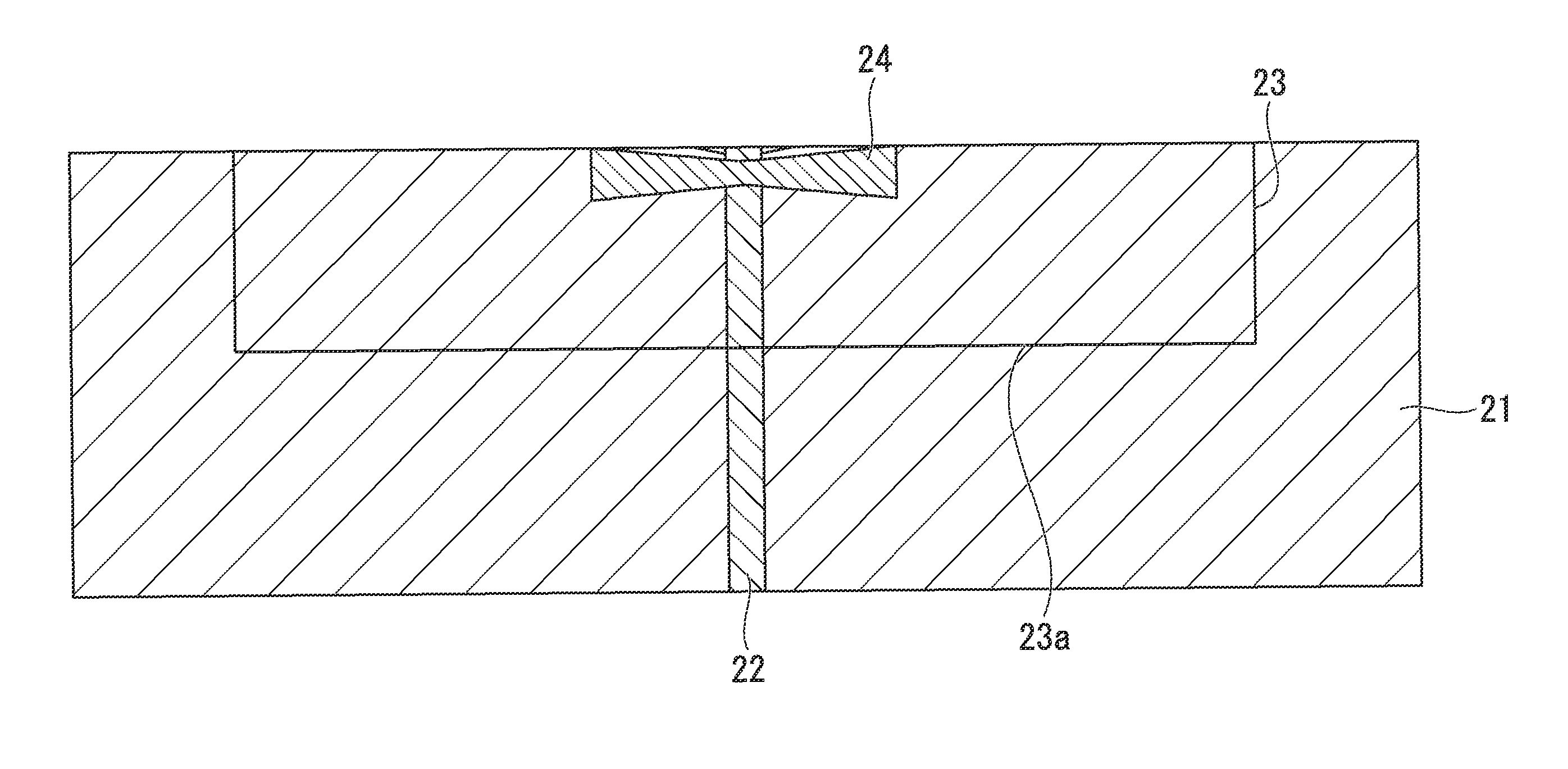
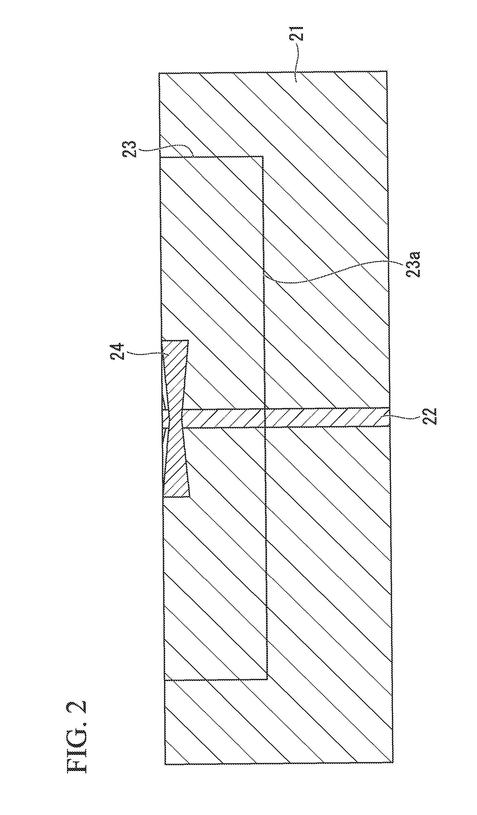
[0088]In the welding joint shown in FIG. 2, it was devised that a joint fatigue test piece 23 was sampled, and a rear surface 23a of the joint fatigue test piece 23 was subjected to mechanical grinding, so that a fatigue crack was generated from a surface side of the test piece. A fatigue test was conducted at an axial force, a stress ratio of 0.1, and a repetition rate of 5 Hz, thereby calculating a fatigue strength at 2×10⁶ cycles. In addition, in the welding joint shown in FIG. 2, an ultrasoni...


PUM

PropertyMeasurementUnit
temperatureaaaaaaaaaa
thicknessaaaaaaaaaa
heightaaaaaaaaaa

Abstract

A welding joint comprises a pair of steel materials, and a welding metal that is formed with a high-energy density beam at a butt welding portion between the pair of steel materials, wherein a transformation starting temperature Ms that is calculated by a following formula: Ms(° C.)=371−353C−22Si−24.3Mn−7.7Cu−17.3Ni−17.7Cr−25.8Mo, using a composition of mass % of the welding metal is 250° C. or less.

Description

FIELD OF THE INVENTION[0001]The present invention relates to a welding joint which may perform butt welding by irradiating a pair of steel materials with a high-energy density beam, and more particularly, to a welding joint which may have excellent fatigue properties in a vibration environment of gigacycle range.[0002]This application is a national stage application of International Application No. PCT / JP2010 / 071721, filed Dec. 3, 2010, which claims priority to Japanese Patent Application No. 2009-277035, filed Dec. 4, 2009, the content of which is incorporated herein by reference.RELATED ART[0003]In recent years, to reduce CO2 gas causing global warming, or to cope with future depletion of fossil fuels such as petroleum, methods of using renewable natural energy have been actively attempted. Wind power is one of these, and large-scale wind power has been spread globally. Areas most suitable for wind power are areas where a strong wind can be expected to blow constant, therefore off...

Claims


Application Information

Patent Timeline
Patent Type & Authority Patents(United States)
IPC IPC(8): B23K9/00C22C38/14C22C38/16B23K35/30B23K15/00B23K15/06B23K26/20B23K26/26F03D1/00C22C38/08B23K35/02C22C38/00C22C38/58F03D13/25
CPCB23K35/30F03D1/001B23K26/26B23K15/006B23K15/0073C22C38/08C22C38/14C22C38/16B23K15/06B23K26/211B23K2201/06B23K2201/18B23K2203/04F05B2230/232Y02E10/728Y02P70/523B23K2101/06B23K2101/18B23K2103/04F03D13/10Y02E10/72Y02P70/50
Inventor ISHIKAWA, TADASHIHONMA, RYUICHIICHIKAWA, KAZUTOSHI
Owner NIPPON STEEL CORP
Why Eureka
Try Eureka