Dryer and water recovery/purification unit employing graphene oxide or perforated graphene monolayer membranes

a technology of graphene oxide and water purification unit, which is applied in the direction of membranes, separation processes, instruments, etc., can solve the problems of water vapor being a major problem for gc/ms systems, system still not functioning perfectly, and the negative influence of the analytical column by water, etc., to facilitate the removal of purified water, improve detection limits, and simplify the analysis of contaminants

Inactive Publication Date: 2016-06-07
LOCKHEED MARTIN CORP
View PDF26 Cites 4 Cited by
  • Summary
  • Abstract
  • Description
  • Claims
  • Application Information

AI Technical Summary

Benefits of technology

[0010]Accordingly, graphene oxide membranes may provide what appears to be a relatively easy solution to water management / recovery issues in analytical chemistry, in spacecraft support systems, and in military and civilian potable water recovery / purification systems. Graphene oxide films, produced from micron-sized flakes of graphene oxide, have the very interesting and useful property of being virtually completely porous to water, but virtually impervious to everything else, even helium. In these applications, it may be desirable to protect the graphene oxide membrane from direct contact with liquid water since such contact may affect the integrity of the film. There are a plurality of ways this can be accomplished without affecting the transport of water vapor through the film. For example, the graphene oxide membrane may be disposed between layers of expanded polytetrafluoroethylene (ePTFE) which allows the passage of water vapor but keeps liquid water from contacting the graphene oxide membrane.
[0019]A water purification and recovery system in which wet muck introduced into the first chamber may be pressurized in order to remove liquid water may be particularly suited to preparing mixed liquid and solid (e.g. wet muck) samples for subsequent analysis. In this regard, by removing water from the wet muck sample such a system reduces the volume of water in the sample thereby increasing the concentration of target analytes to improve analytical results / sensitivity.

Problems solved by technology

The analytical column may be negatively affected by water.
In this regard, water vapor is a major problem for GC / MS systems, and must be eliminated as much as possible from the sample being injected for analysis.
However, those systems still do not function perfectly, and they add an additional several minutes to the analytical time for every sample while they cycle to remove the water.
It worked well for a lot of compounds, but fell short for polar compounds.
It worked well for a number of toxic substances, but many of the polar toxic substances were lost through the Nafion® to such a degree that the method was eventually replaced.
The water management system takes several minutes to cycle, and that delays the injection of the sample.
While this type of system, which is the current state of the art, is successful, the dilution / pressurization step takes time and introduces the possibility of error.
The presence of high levels of humidity in the air detracts from the ability of some carbon dioxide removal systems to work at peak efficiency.
Additionally, water can be difficult and / or energy expensive to remove from waste while providing sufficient purity for re-use as drinking water.
Many types of systems for providing potable water are either heavy and require substantial energy input, or have substantial limitations on the types of contamination for which they work properly.
Additionally, water samples collected for analysis often contain trace levels of toxic substances.
There is a partition coefficient between the water sample and the extraction medium that sets a lower limit of concentration of the trace toxic substance below which the quantitative nature of the extraction is substantially less than complete, and the accuracy of the analysis is affected detrimentally.

Method used


Image

  • Dryer and water recovery/purification unit employing graphene oxide or perforated graphene monolayer membranes
  • Dryer and water recovery/purification unit employing graphene oxide or perforated graphene monolayer membranes
  • Dryer and water recovery/purification unit employing graphene oxide or perforated graphene monolayer membranes

Examples


Embodiment Construction

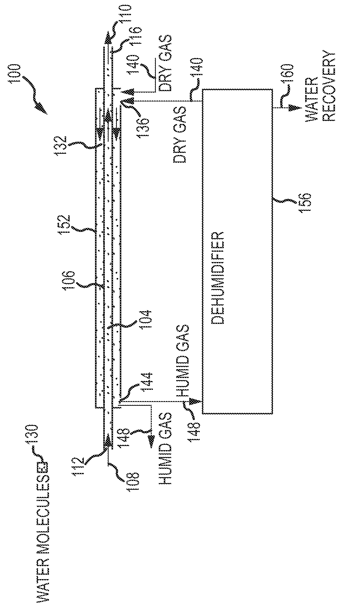
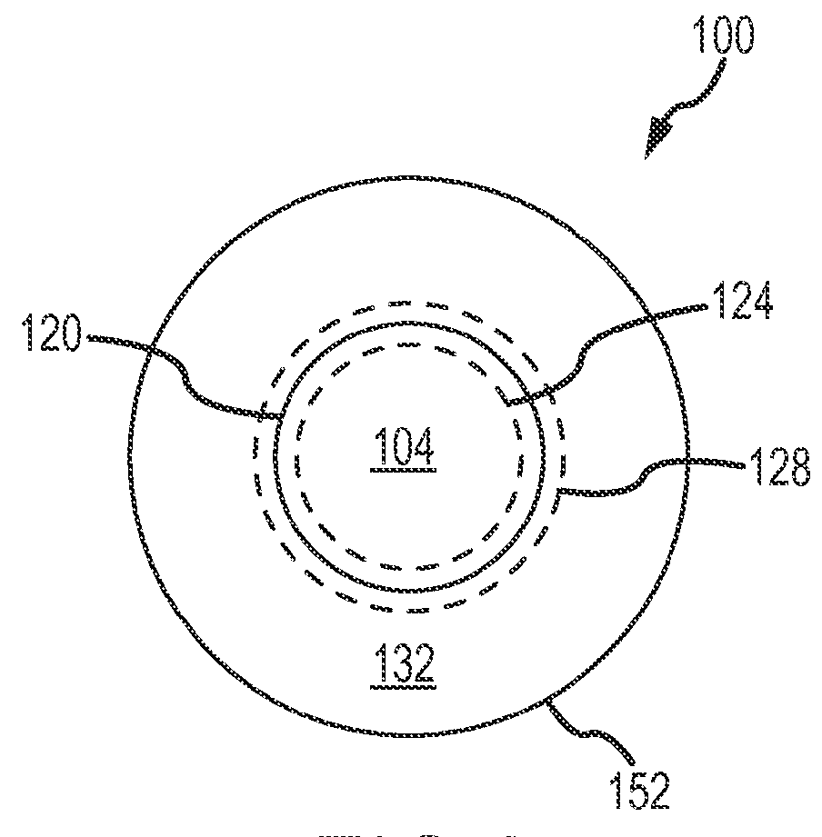
[0026]Referring to FIGS. 1 and 2, side and cross-sectional views are presented of one embodiment of a graphene oxide dryer unit 100 useful in removing water vapor from a humid gas. The graphene oxide dryer 100 may also function as a water recovery unit for recovering water from a humid gas and / or from a liquid. Broadly, the graphene oxide dryer 100 may include any appropriate structure providing at least two lumens (e.g., a double-walled pipe, a tube within a shell, a tube with a longitudinal separation plate, etc.). In the present embodiment, the graphene oxide dryer 100 may include a first lumen 104 that may receive a humid gas stream 108 at first opening 112 of the first lumen 104 and expel dehumidified gas 110 at a second opening 116 of the first lumen 104.

[0027]The first lumen 104 may be provided within the interior of an inner tube 106. The inner tube 106 may include one or more concentric layers that extend for all or a portion of the length of first lumen 104, one layer of w...


PUM

PropertyMeasurementUnit
chemical analysisaaaaaaaaaa
gas chromatographaaaaaaaaaa
mass spectrometeraaaaaaaaaa

Abstract

Apparatuses and systems for removing water vapor from a gas stream and for providing water purification, recovery and / or concentration. The apparatuses and systems employ a graphene oxide or a perforated graphene monolayer membrane to separate liquid water molecules and / or water vapor molecules from gasses, liquids, and other substances such as a wet muck or an aqueous sample. In one embodiment, an apparatus for removing water from a gas or liquid stream includes a first lumen, a second lumen, and a graphene oxide membrane separating the first lumen from the second lumen. Water molecules within a humid gas or liquid stream introduced into the first lumen pass through the graphene oxide membrane into a dry gas stream introduced into the second lumen.

Description

RELATED APPLICATION INFORMATION[0001]This application claims priority to U.S. Provisional Application Ser. No. 61 / 816,052, entitled “GRAPHENE OXIDE DRYER AND WATER RECOVERY / PURIFICATION UNIT” filed on Apr. 25, 2013, the entire contents of which are incorporated by reference herein as if set forth in full.FIELD OF THE INVENTION[0002]The present invention relates generally to the removal and recovery of water from gases, liquids and other substances.BACKGROUND OF THE INVENTION[0003]The chemical analysis of trace quantities of toxic substances by gas chromatograph / mass spectrometer (GC / MS) instruments requires the concentration of those substances on a trap, and subsequent release of those substances into an analytical column to separate the substances from each other on the way to the mass spectrometer. The analytical column may be negatively affected by water. In this regard, water vapor is a major problem for GC / MS systems, and must be eliminated as much as possible from the sample ...

Claims


Application Information

Patent Timeline
Patent Type & Authority Patents(United States)
IPC IPC(8): B01D71/02B01D53/22B01D71/06B01D53/26B01D63/06C02F1/44C02F11/12G01N30/14C02F11/13C02F103/20
CPCB01D71/021B01D53/228B01D53/268B01D63/06B01D71/06C02F1/447B01D71/024B01D2258/0266B01D2311/103B01D2313/23C02F11/12C02F2103/20G01N2030/146C02F11/13
Inventor WOOD, JOHN A.SCHWARTZ, REBECCALILLY, PAUL J.
Owner LOCKHEED MARTIN CORP
Why Eureka
Try Eureka