Millimeter-sized recognition signal badge and identification system for accurately discerning and sorting among similar kinds, shapes, and sizes of surgical instruments

a recognition signal and millimeter-sized technology, applied in the field of millimeter-sized recognition signal badge and identification system for accurately discerning and sorting among similar kinds, shapes and sizes of surgical instruments, can solve the problems of extending the life of the needle holder, and affecting the operation efficiency of the instrumen

Active Publication Date: 2016-06-21
SUMMATE TECH INC
View PDF31 Cites 4 Cited by
  • Summary
  • Abstract
  • Description
  • Claims
  • Application Information

AI Technical Summary

Benefits of technology

[0095]a millimeter-sized three-sheet stack construct which protects against the undesirable effects of impact forces and safeguards its internal contents from degradation by the ambient environment, said millimeter-sized three-sheet stack construct being formed of
[0110]a millimeter-sized three-sheet stack construct which protects against the undesirable effects of impact forces and safeguards its internal contents from degradation by the ambient environment, said millimeter-sized three-sheet stack construct being formed of

Problems solved by technology

The same difficulty hold true for retractors, needle holders, and many other kinds of surgical tools.
The inserts can be replaced as they wear down, which prolongs the life of the needle holder and defrays the replacement cost of an entire instrument.
However, such surgical scissors should never be used to cut paper or tubing; instead, bandage scissors are to be utilized for this purpose.
Consequently, in order to keep track of which arrangement a particular surgical instrument or tool rightly belongs to, several instrument identification techniques have been attempted over time, which have had only modest degrees of success.
Nevertheless, because the tape label is directly exposed to a cycle of surgical use, then to the harsh washing / drying cycles, and finally to severe sterilization repetitiously over and over again—the original color codes fade and become blanched, and the original configured shapes fray and shred over time.
Furthermore, manual check-off lists for instrument tray assembly is very time consuming, and plagued by inaccuracies.
Also, hospitals have to spend considerable resources in developing human instrument specialists for the job of assembling specific surgical instrument trays.
However, although now widely accepted in commerce and commonly used in inventory control merchandising, there are many major obstacles which meaningfully bar and prevent a functional use of barcode labels with surgical instruments and tools; which include all of the following:
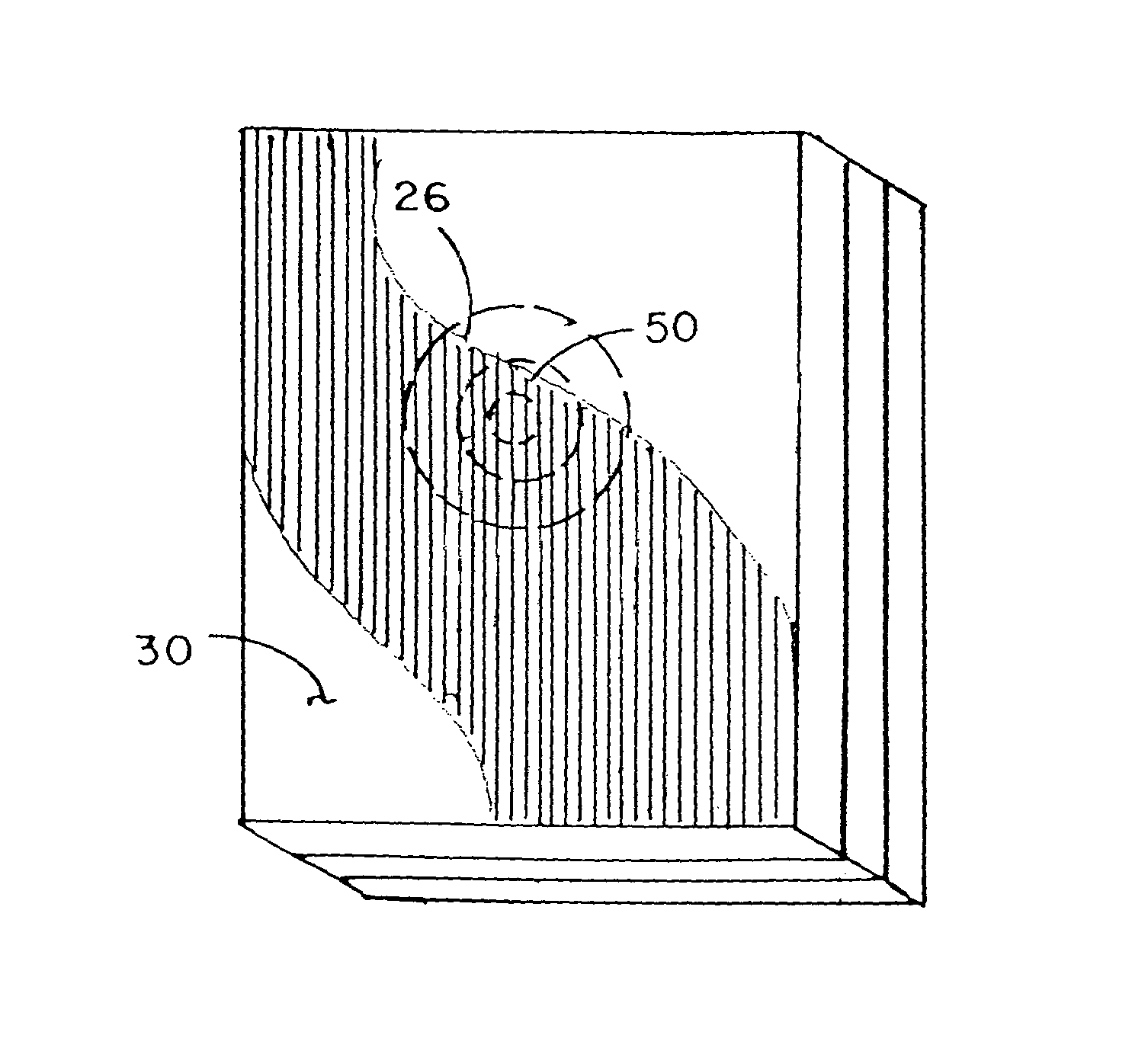
To be operative, the barcode identification label must be placed on a relatively flat surface which is fully exposed and is visibly viewable—or the existing scanning technology will not be able to read the bar code, as the scanner / reader cannot get a complete or accurate image of the complete barcode itself.
However, many surgical instruments and tools have very little exposed surface area that is flat or a planar surface.
Two dimensional barcodes, which are smaller, also have similar problems as they need to be scanned in two dimensions on a flat surface, which will not work on the small round dimensions of many surgical instruments.
For any barcode label system to be useful in identifying surgical instruments in trays, all the pre-chosen instruments of each respective tray must be able to be scan-identified, otherwise the desired tray arrangement will not be accurately assembled.
For these reasons, hospitals and clinic have generally been compelled to apply barcode identification systems only at the “pallet” or assembled tray level; but have been markedly hampered and routinely disappointed when attempting to apply barcode identification labels directly to the individual instruments assembled within a single surgical instrument tray.
As a result, the current use of such barcode identification systems still cannot and does not avoid the presence of a wrong or mis-chosen instrument in surgical instrument tray assemblies; and the problem today still remains a serious and continuing challenge waiting to be solved.
However, once a lithium battery goes dead, the entire CMOS chip must be replaced.
However, batteries and solenoids are relatively bulky items; and therefore require the size of electronic transponders to be quite large in its minimal dimensions and volume.
The presence of the requisite antenna, however, further increases the overall size of the transponder.
Yet, despite their overall bulk volume and relatively large dimensions, transponders are employed for some unusual and unexpected applications.
Unfortunately, such protective enclosures merely add more dimensional size and greater volume to the previously existing bulk and girth of the transponder unit.
RFID technology has been conventionally known and used since about 1970; but it has generally been too cumbersome and expensive to use on a large scale, and thus has not been a commercial success to date.
However, this 2nd generation tag technology never was accepted with retailers, and the commercial production of BiStatix RFID tags ended in 2001.
Active and semi-passive forms of RFID tags contain more hardware than passive RFID tags; and for this reason, the active and semi-passive forms are considerably more expensive to manufacture.
Because passive RFID tags rely entirely on the electromagnetic field generated by the external reader as their sole power source, they are very limited in their broadcast distances.
Consequently, there is no such thing as a miniaturized FRID transponder unit; and to date, it has been impossible to make a truly small-sized RFID transponder as such.
For all these reasons, all RFID transponders regardless of type are of-necessity modestly large in both dimensional size and overall volume; and consequently cannot be fitted onto any small-sized area or minimal available surface.

Method used


Image

  • Millimeter-sized recognition signal badge and identification system for accurately discerning and sorting among similar kinds, shapes, and sizes of surgical instruments
  • Millimeter-sized recognition signal badge and identification system for accurately discerning and sorting among similar kinds, shapes, and sizes of surgical instruments
  • Millimeter-sized recognition signal badge and identification system for accurately discerning and sorting among similar kinds, shapes, and sizes of surgical instruments

Examples


Embodiment Construction

[0144]The present invention is a discrete signal-emitting badge and operative system for recognizing, differentiating and distinguishing among the many kinds, shapes and sizes of surgical instruments and tools commonly used today for human and veterinary surgeries. The signal-emitting badge is a discrete millimeter-sized article of manufacture which can be easily affixed to an exposed surface of any type, any configuration and any dimension of surgical instrument or tool; and includes a well-cushioned and protected photovoltaic cell-integrated chip transponder unit embedded within a safeguarding three-tier stack construct. The photovoltaic cell of the embedded transponder is activated by the introduction of light energy in any form; and once activated, provides electric power to the electronic circuitry of the transponder unit of the instrument-affixed badge such that a responsive identifying RF signal is emitted to the ambient atmosphere. That emitted responsive identifying RF sign...


PUM


Abstract

The present invention is a discrete signal-identifying badge and operative system for recognizing, differentiating and distinguishing among the many kinds, shapes and sizes of surgical instruments and tools commonly used today for human and veterinary surgeries and in scientific research. The signal-identifying badge is a discrete millimeter-sized article of manufacture which can be easily affixed to an exposed surface of any type, any configuration and any dimension of surgical instrument or tool; and includes a well-cushioned and protected photovoltaic cell-integrated chip transponder unit embedded within a safeguarding three-tier stack construct.

Description

FIELD OF THE INVENTION[0001]The present invention is generally concerned with the application of Complementary Metal Oxide Semiconductor (CMOS) chip technologies which are electronically able to broadcast recognition signals for object identification and sorting purposes; and is particularly directed to the use of such CMOS chip technology for a millimeter-sized recognition signal badge and object identification system by which to differentiate and distinguish accurately among similar kinds, shapes, and sizes of surgical instruments and tools used today for performing a variety of human and veterinary surgical procedures.BACKGROUND OF THE INVENTIONSurgical Tools and Instruments[0002]Surgical tools and instruments intended for use in human and veterinary surgery are typically sorted and organized into tray arrangements by: (i) specified surgical procedure, (ii) surgeon preferences for a type and variety of instruments, and (iii) the particular anatomic area or part of the human body ...

Claims


Application Information

Patent Timeline
Patent Type & Authority Patents(United States)
IPC IPC(8): G06F19/00G06K19/077G06K7/10G06K19/073G06K19/07G06K17/00
CPCA61B90/98G06K7/1097G06K19/0723G06K19/07345G06K19/07758G06K2017/0045A61B90/90
Inventor SAYLES, PHILIP W.
Owner SUMMATE TECH INC
Why Eureka
Try Eureka