Electrostatic electroacoustic transducer and fabricating methods for the same
a transducer and electroacoustic technology, applied in the direction of piezoelectric/electrostrictive transducers, transducer types, electrostatic transducers of semiconductor types, etc., to achieve the effect of dramatically improving the intensity of electric field between the diaphragm and the driving element, promoting efficiency and bandwidth of the diaphragm, and reducing the thickness of the diaphragm
- Summary
- Abstract
- Description
- Claims
- Application Information
AI Technical Summary
Benefits of technology
Problems solved by technology
Method used
Image
Examples
first embodiment
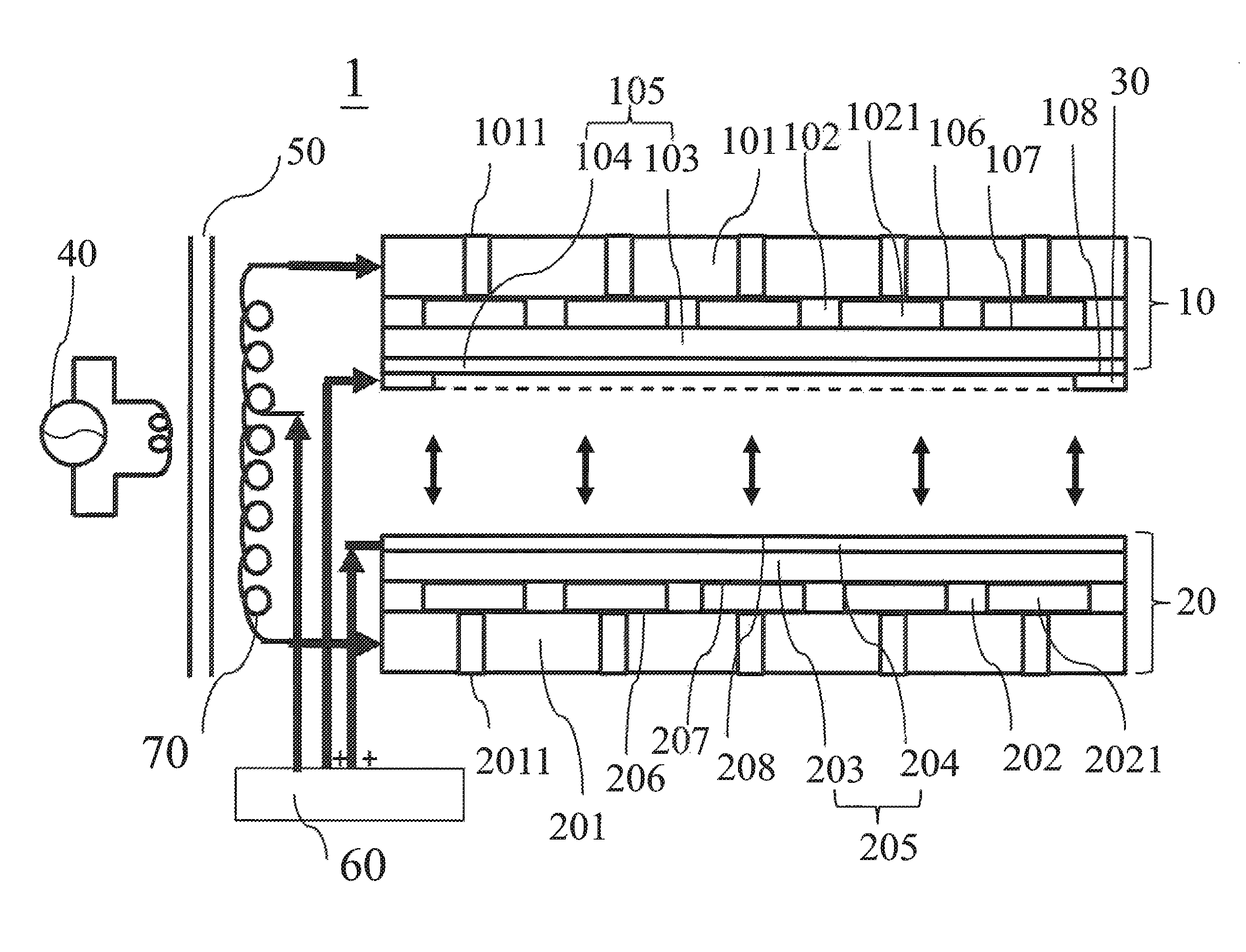
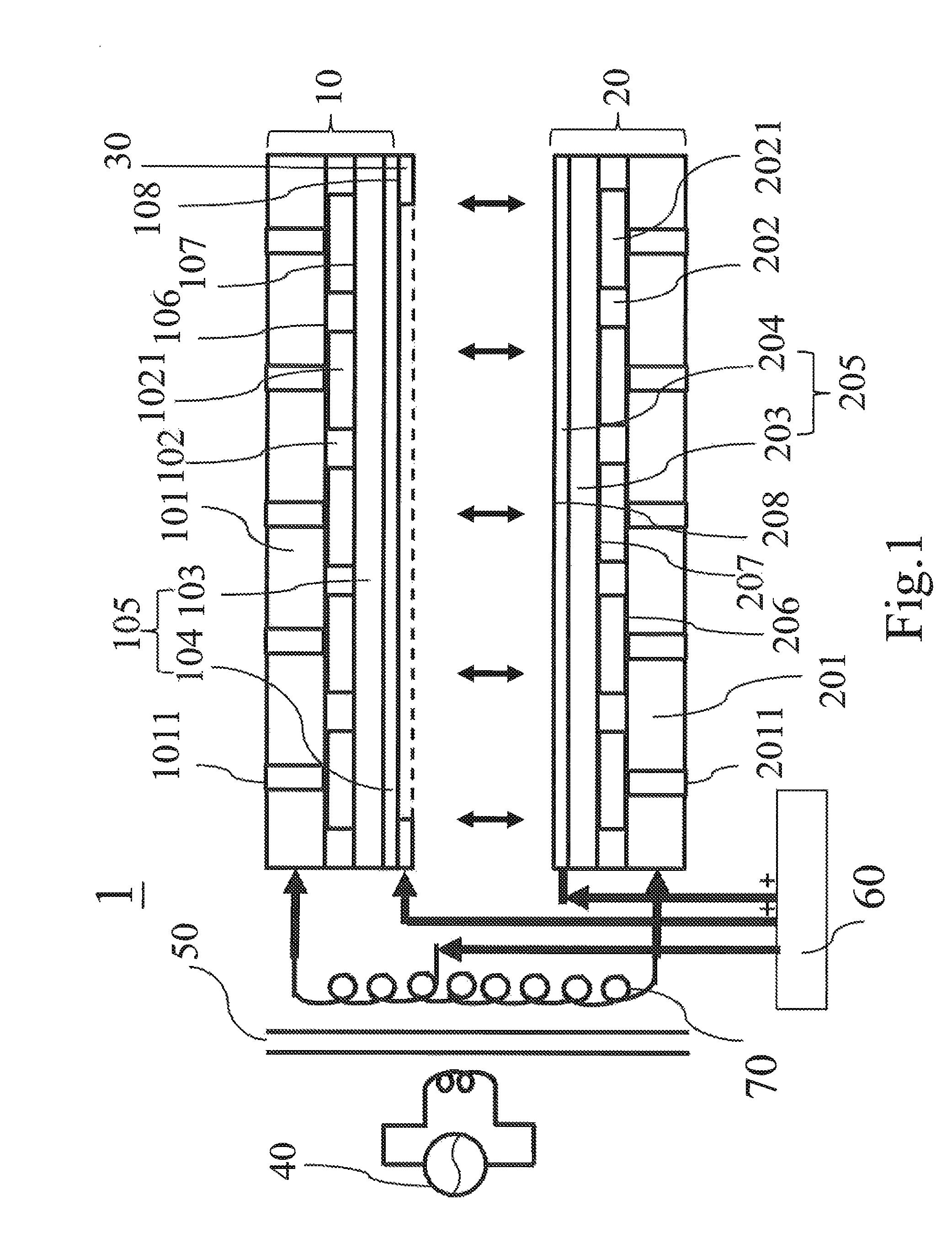
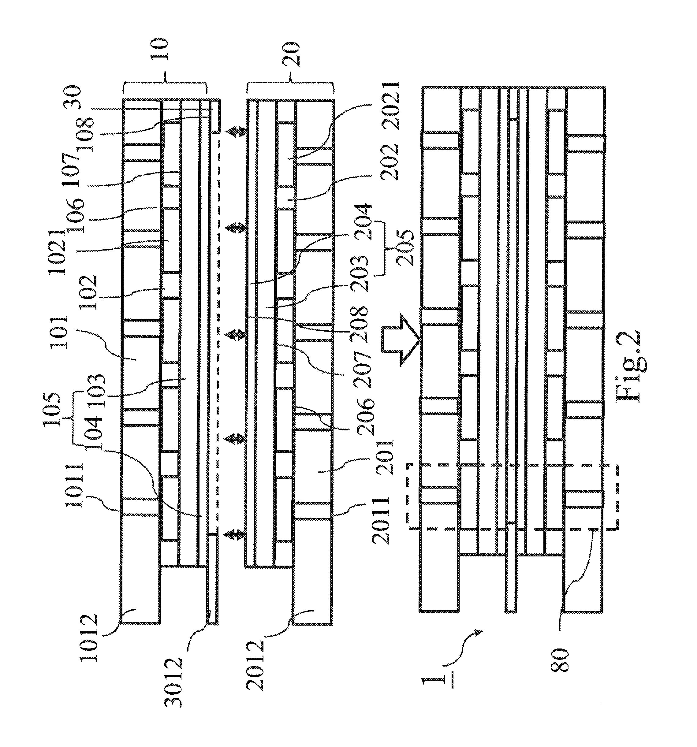
[0023]Please refer to FIG. 1, FIG. 2, FIG. 3 and FIGS. 4A-4C, the electrostatic electroacoustic transducer 1 according to the present invention comprises a first structure 10, a second structure 20 and a third electrode 30, wherein the third electrode 30 is located between the first structure 10 and the second structure 20. The first structure 10 includes a first driving element 101, a first spacer 102 and a first diaphragm 105; the second structure 20 includes a second driving element 201, a second spacer 202 and a second diaphragm 205, wherein the first diaphragm 105 has a first dielectric 103 and a first electrode 104, and the second diaphragm 205 has a second dielectric 203 and a second electrode 204. When the first structure 10, the second structure 20 and the third electrode 30 are assembled into the electrostatic electroacoustic transducer 1 having a dual-diaphragm structure, as shown in FIG. 2, the first structure 10 and the second structure 20 show a mirror-inverted arrange...
second embodiment
[0029]Please refer to FIG. 1, FIG. 2, FIGS. 6A and 6B for operations of the electrostatic electroacoustic transducer in the sounding region 80 according to the present invention. In the case that the alternating voltage 40 provides a negative potential to the first driving element 101 and a positive potential to the second driving element 201, and the third binders 108, 208 are non-conductive paste, a bias is applied to the second electrode 204 and third electrode 30 so that both have positive potentials. Accordingly, the first electrode 104 shows polarization effect due to the inductive charges of the third electrode 30. Due to the first electrode 104, the first dielectric 103 also produces inductive charges and shows polarization effect. As a result, one end of the first dielectric 103 close to the first driving element 101 has a positive potential, which is in turn attracted by the negative potential of the first driving element 101. On the other hand, the second dielectric 203 p...
third embodiment
[0030]Please refer to FIG. 1, FIG. 2, FIGS. 7A and 7B for operations of the electrostatic electroacoustic transducer in the sounding region 80 according to the present invention. In the case that the alternating voltage 40 provides negative potentials to both of the first driving element 101 and second driving element 201, and the third binders 108, 208 are non-conductive paste, the bias voltage 60 is applied to the second electrode 204 and third electrode 30 so that the second electrode 204 has a negative potential and the third electrode 30 has a positive potential. Accordingly, the first electrode 104 shows polarization effect due to the inductive charges of the third electrode 30. Due to the first electrode 104, the first dielectric 103 also produces inductive charges and shows polarization effect. As a result, one end of the first dielectric 103 close to the first driving element 101 has a positive potential, which is in turn attracted by the negative potential of the first dri...
PUM
 Abstract
Description
Claims
Application Information
 - R&D
- Intellectual Property
- Life Sciences
- Materials
- Tech Scout
- Unparalleled Data Quality
- Higher Quality Content
- 60% Fewer Hallucinations
Browse by: Latest US Patents, China's latest patents, Technical Efficacy Thesaurus, Application Domain, Technology Topic, Popular Technical Reports.
© 2025 PatSnap. All rights reserved.Legal|Privacy policy|Modern Slavery Act Transparency Statement|Sitemap|About US| Contact US: help@patsnap.com


