Precision substrate material removal using miniature-column charged particle beam arrays

a technology of charged particle beams and substrates, which is applied in the direction of vacuum evaporation coating, semiconductor/solid-state device testing/measurement, coatings, etc., can solve the problems of reducing errors, reducing the cost of advanced process nodes. , to achieve the effect of increasing the specificity and quantity of collected gasses, reducing the cost of manufacturing, and reducing the number of steps

Active Publication Date: 2016-10-11
MULTIBEAM CORP
View PDF4 Cites 12 Cited by
  • Summary
  • Abstract
  • Description
  • Claims
  • Application Information

AI Technical Summary

Benefits of technology

[0022]In particular, the inventors have discovered that etching and milling using charged particle beam columns can be accelerated by multiple orders of magnitude by using local injectors fixedly located with respect to corresponding ones of the columns, and proximate, oriented towards and having line of sight to corresponding ones of the frames.
[0023]Innovatively, local photon injectors can be used to precisely heat the locations targeted by the charged particle beams, to thereby tune the adsorption rate of the targeted material; to shine photons with a chemistry-characteristic wavelength on the locations targeted by the charged particle beams to tune reaction rate and / or efficiency; and to provide photons reflected or emitted from the substrate surface to local photon detectors for analysis.
[0024]Further innovatively, local gas injectors connected to kinetic lenses (collimating or redirecting gas particles towards the frame) can be used to raise partial pressure of process-critical gasses (e.g., oxidizing or reducing gasses) by orders of magnitude over the average ambient pressure in the vacuum chamber to increase reaction rate.
[0025]The inventors have also discovered that local photon detectors and gas detectors, situated locally to and collecting data directly from beam target locations, can be used to monitor and provide feedback to control of charged particle beam columns performing material subtraction processes, including for example process endpoint detection. Local gas detectors can use kinetic lenses to increase specificity and quantity of collected gasses.
[0026]Preferred embodiments of miniature column charged particle beam material subtraction include material removal (e.g., etching / milling), control and inspection processes that can work directly and automatically from the SAME design layout database. In some embodiments, these and other processes can be implemented together within a single modular tool, allowing patterning of entire layers without breaking vacuum.
[0027]Material subtraction processes can be used to replace conventional resist-pattern-develop-etch lithography processes for some or all substrate layers to eliminate numerous lithography steps, increase throughput and dramatically increase yield.

Problems solved by technology

Fabrication of an optical mask typically takes weeks and costs millions of dollars at advanced process nodes.
Yield-reducing errors can be reduced by other tools, adding additional steps, and potentially additional defects.

Method used


Image

  • Precision substrate material removal using miniature-column charged particle beam arrays
  • Precision substrate material removal using miniature-column charged particle beam arrays
  • Precision substrate material removal using miniature-column charged particle beam arrays

Examples


Embodiment Construction

[0048]The numerous innovative teachings of the present application will be described with particular reference to presently preferred embodiments (by way of example, and not of limitation). The present application describes several inventions, and none of the statements below should be taken as limiting the claims generally.

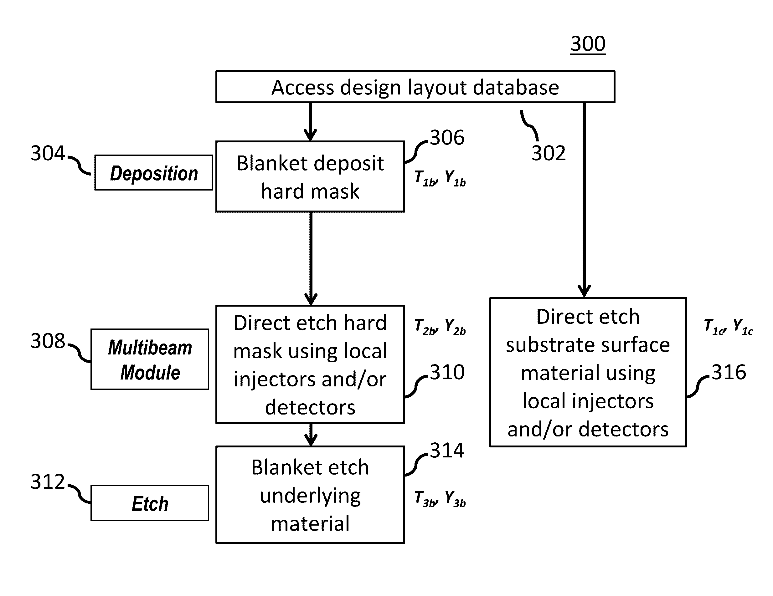
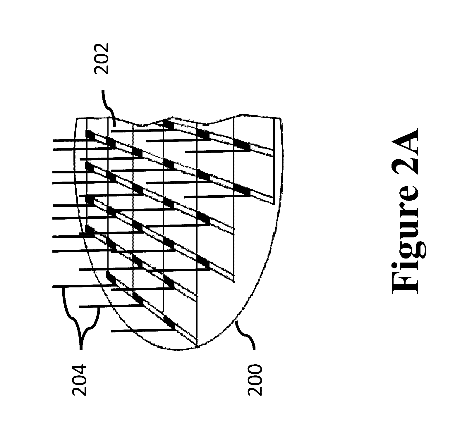
[0049]The present application discloses new approaches to systems, devices and methods for precision removal of material from a substrate 404 using multiple miniature charged particle columns 206 configured to perform material subtraction directly on hard mask, substrate pattern layer and other materials WITHOUT A RESIST LAYER.

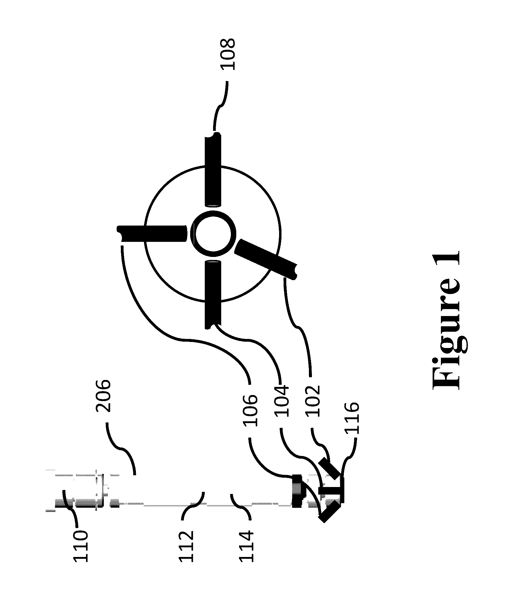
[0050]In particular, the inventors have discovered that material removal (e.g., etching and / or milling) using charged particle beam columns 206 can be accelerated by multiple orders of magnitude by using local injectors 102, 104 fixedly located with respect to corresponding ones of the columns 206, and proximate, oriented towards and having...


PUM

PropertyMeasurementUnit
reaction rateaaaaaaaaaa
areasaaaaaaaaaa
partial pressureaaaaaaaaaa

Abstract

Methods, devices and systems for patterning of substrates using charged particle beams without photomasks and without a resist layer. Material can be removed from a substrate, as directed by a design layout database, localized to positions targeted by multiple, matched charged particle beams. Reducing the number of process steps, and eliminating lithography steps, in localized material removal has the dual benefit of reducing manufacturing cycle time and increasing yield by lowering the probability of defect introduction. Furthermore, highly localized, precision material removal allows for controlled variation of removal rate and enables creation of 3D structures or profiles. Local gas injectors and detectors, and local photon injectors and detectors, are local to corresponding ones of the columns, and can be used to facilitate rapid, accurate, targeted substrate processing.

Description

CROSS-REFERENCE[0001]Priority is claimed from, and this application is a non-provisional of, Provisional Pat. App. No. 62 / 107,332, filed Jan. 23, 2015; Provisional Pat. App. No. 62 / 115,626, filed Feb. 12, 2015; and Provisional Pat. App. No. 62 / 151,225, filed Apr. 22, 2015, which are hereby incorporated by reference.BACKGROUND[0002]The present application relates to systems, devices and methods for maskless material removal from substrates using charged particle beams; and more particularly to directly removing material from precise locations as defined in a design layout database using multiple, matched charged particle beams, with the assistance of gas and / or photon injection, and / or of gas and / or photon process control, metrology and endpoint detection.[0003]Note that the points discussed below may reflect the hindsight gained from the disclosed inventions, and are not necessarily admitted to be prior art.[0004]FIG. 2A shows an example of a wafer 200 being scanned by multiple char...

Claims


Application Information

Patent Timeline
Patent Type & Authority Patents(United States)
IPC IPC(8): H01J37/30H01J37/05H01J37/22H01J37/305H01J37/304H01J37/317
CPCH01J37/30H01J37/305H01J37/3177H01J37/3056H01J37/3053H01J37/228H01J37/05H01J37/304H01J2237/004B81C2201/0143H01J2237/0635H01J2237/30472H01J2237/1501B81C2201/0188B81C1/00373C23C16/047H01J37/3178C23C16/486C23C16/487H01J2237/31732H01J2237/30466H01J2237/3174H01J37/08H01J2237/31737H01J2237/31735H01J37/244H01J37/06C23C16/48H01J2237/24592H01J2237/31749H01L21/26H01L21/3065H01L21/308H01L22/12H01L22/20H01L22/26H01J37/3172H01J37/3174H01J2237/31708H01L21/3085C23C14/48H01L21/0228H01L21/0262
Inventor LAM, DAVID K.MONAHAN, KEVIN M.SMAYLING, MICHAEL C.PRESCOP, THEODORE A.
Owner MULTIBEAM CORP
Why Eureka
Try Eureka