
Systems and methods for additive manufacturing and repair of metal components

a technology of metal components and additive manufacturing, applied in the field of systems and methods for additive manufacturing and metal component repair, can solve problems such as creating previously unattainable single crystals

Active Publication Date: 2016-12-20
GEORGIA TECH RES CORP
View PDF11 Cites 113 Cited by
  • Summary
  • Abstract
  • Description
  • Claims
  • Application Information

AI Technical Summary

Benefits of technology

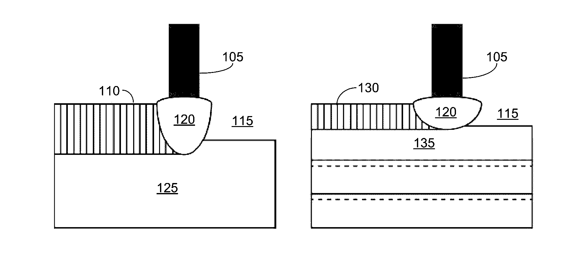
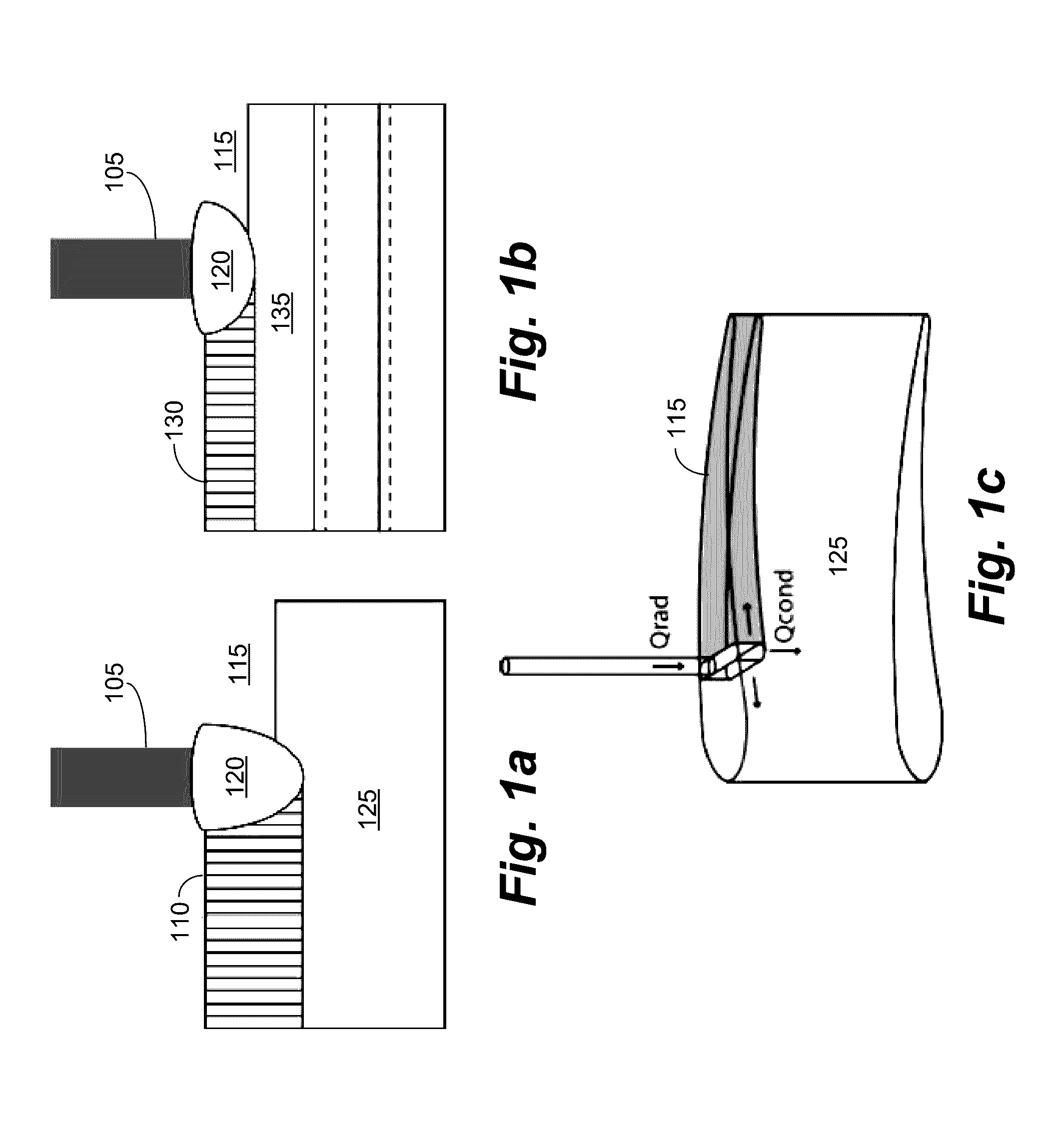
The invention is a system and method for repairing existing parts and creating new parts using laser sintering of metals. The system includes a laser, a bed of powdered material, a chamber, a mirror, and a vacuum pump. The laser melts the powdered metal to fuse it to layers underneath, repairing cracks and creating fully functional parts. The process involves scanning the powder with a laser beam and controlling laser parameters in real-time to control grain growth and cooling rates. This system can create macromorphological structures with pre-defined microstructural features.

Problems solved by technology

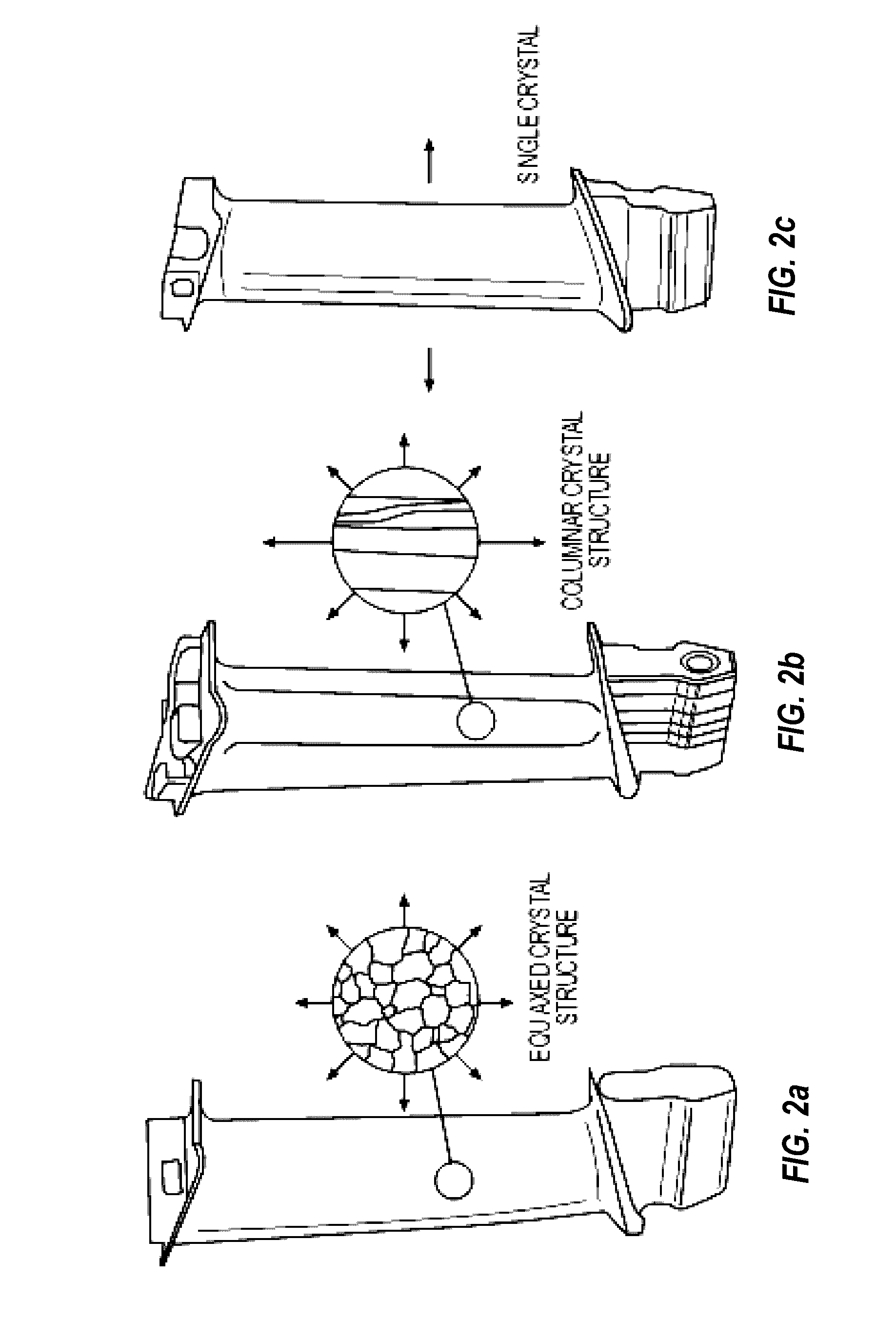
This, in turn, can create previously unattainable single-crystal and directionally solidified microstructures in additive manufacturing.

Method used


Image

  • Systems and methods for additive manufacturing and repair of metal components
  • Systems and methods for additive manufacturing and repair of metal components
  • Systems and methods for additive manufacturing and repair of metal components

Examples


example

[0334]The Canny edge detection algorithm was run on several trial processing applications and found to have a computation time on the order of 100-150 ms for a 640×480 pixel thermal image on a modern Intel Core2Duo CPU. This computation time lowered the usable rate of the thermal imaging camera from 50-60 FPS to approximately 30 FPS. Although the thermal imaging camera would typically be used at a limited rate of 30 FPS in the real-time control algorithms, the Canny edge detection algorithm used relatively large amounts of CPU resources and limited the available computational power that could be used in the real-time controller itself. In some embodiments, therefore, due to these constraints, a more efficient blob detection algorithm can be used, as described below.

[0335]Connected Contour Labeling Algorithm

[0336]A second blob detection algorithm operated in linear time and was based upon the work of Chang, Chen, and Lu and Liñán.1 The algorithm operates by sending scan lines or rays...


PUM

PropertyMeasurementUnit
temperatureaaaaaaaaaa
frequencyaaaaaaaaaa

Abstract

Scanning Laser Epitaxy (SLE) is a layer-by-layer additive manufacturing process that allows for the fabrication of three-dimensional objects with specified microstructure through the controlled melting and re-solidification of a metal powders placed atop a base substrate. SLE can be used to repair single crystal (SX) turbine airfoils, for example, as well as the manufacture functionally graded turbine components. The SLE process is capable of creating equiaxed, directionally solidified, and SX structures. Real-time feedback control schemes based upon an offline model can be used both to create specified defect free microstructures and to improve the repeatability of the process. Control schemes can be used based upon temperature data feedback provided at high frame rate by a thermal imaging camera as well as a melt-pool viewing video microscope. A real-time control scheme can deliver the capability of creating engine ready net shape turbine components from raw powder material.

Description

CROSS REFERENCE TO RELATED APPLICATIONS[0001]This application claims benefit, under 35 U.S.C. §119(e) to U.S. Provisional Applications No. 61 / 724,035 filed Nov. 8, 2012, which is incorporated herein as if set forth below.STATEMENT REGARDING FEDERALLY SPONSORED RESEARCH[0002]The present invention was made with United States Government support under contract number N00173-07-1-0031 awarded by the U.S. Naval Research Lab. The United States Government has certain rights in the present invention.BACKGROUND OF THE INVENTION[0003]1. Field of the Invention[0004]Embodiments of the present invention relate generally to a system method for using a directed beam of energy to selectively sinter metal powder to produce or repair a part; and specifically, to the use of selective laser sintering (SLS) and scanning laser epitaxy (SLE) to produce or repair a full density metal part.[0005]2. Background of Related Art[0006]Since its inception in the 1930's, the gas turbine engine has grown to be the wo...

Claims


Application Information

Patent Timeline
Patent Type & Authority Patents(United States)
IPC IPC(8): G06F19/00B22F5/00B22F5/04B29C67/00C30B13/24C30B29/52B22F3/105B23P6/00B22F7/06B29L31/08
CPCB22F3/1055B22F5/009B22F5/04B29C67/0077C30B13/24C30B29/52B22F2003/1057B22F2007/068B23P6/007B29L2031/08Y02P10/295B29C64/153B33Y70/00B33Y80/00B33Y30/00B33Y10/00G01J2005/0077G01J5/004Y02P10/25B33Y50/02B22F2999/00B22F10/28B22F10/36B22F10/366B22F12/41B22F12/90B22F2203/03B22F2203/11B22F7/062C30B13/28C30B13/32C30B19/08C30B19/10
Inventor DAS, SUMANBANSAL, ROHANGAMBONE, JUSTIN
Owner GEORGIA TECH RES CORP
Learn More