Piston arrangement and internal combustion engine

a technology of piston arrangement and internal combustion engine, which is applied in the direction of machines/engines, combustion air/fuel air treatment, mechanical equipment, etc., can solve the problems of reducing efficiency, reducing engine speed limit, engine performance, etc., and achieves efficient lubrication, less susceptible to wear, and reduced engine running cost

Active Publication Date: 2017-04-04
OXFORD TWO STROKE
View PDF49 Cites 3 Cited by
  • Summary
  • Abstract
  • Description
  • Claims
  • Application Information

AI Technical Summary

Benefits of technology

[0010]By connecting the shaft to the piston via a shuttle bearing (as opposed to a conventional crankshaft and con-rod arrangement), the power transfer assembly allows better control of piston motion and the reduced acceleration spikes. For example, TDC piston acceleration may be reduced and TDC dwell time may be increased. Reducing TDC piston acceleration reduces peak loading of the transfer assembly, and therefore wear rates are reduced and the weight of the power transfer assembly components can be minimised. When the invention is applied to an internal combustion engine, increasing TDC dwell time increases combustion efficiency and allows a reduction in spark advance for spark ignition engines or increased maximum engine speed for compression ignition engines. Reducing or eliminating the difference between TDC and BDC acceleration also allows a counterbalancing system to be optimised bore efficiently top control vibrations at TDC and BDC.
[0012]By allowing rotation of the shuttle bearing about the second axis the shuttle bearing can maintain good contact with the piston in the case of slight misalignment of any of the components in the power transfer assembly. The piston arrangement is therefore better able to withstand misalignment of components due to manufacturing errors and / or uneven wear of components. The piston arrangement is also less susceptible to wear. The curvature of the bearing surface allowing rotation of the shuttle bearing about the second axis may have an arc which extends through an angle of at least 1°, or at least 2°, or at least 5°, or at least 10°, or at least 15°, or at least 20°. The curved bearing surface may extend up to 360° around the entire shuttle bearing. The degree of rotation of the shuttle bearing about the second axis during operation of the engine is, of course, limited by the other components in the power transfer assembly.
[0013]By rotating the shuttle bearing about the third axis the piston displacement may be controlled. For example, piston acceleration about TDC may be further reduced thereby decreasing peak loading and further increasing TDC dwell time. The curvature of the bearing surface allowing rotation of the shuttle bearing about the third axis may have an arc which extends through an angle of at least 1°, or at least 2°, or at least 5°, or at least 10°, or at least 15°, or at least 20°. The degree of rotation of the shuttle bearing about the third axis during operation of the engine is, of course, limited by the other components in the power transfer assembly.
[0020]At least one bearing surface of the piston and / or shuttle bearing may comprise one or more groves formed therein. The grooves may be substantially straight, curved, chevron shaped or take any other suitable form. The grooves may assist with hydrodynamic lubrication, improving the distribution of lubricant between the shuttle bearing and the piston and reducing sliding friction and wear at the bearing surfaces.
[0037]The power transfer assembly may be housed within an intermediate chamber located between the first and second chambers. The intermediate chamber may be sealed to substantially prevent the passage of fluid past the first and / or second head into or out of the first and / or second chambers.
[0038]By locating the power transfer mechanism between the working head and the shaft in the intermediate chamber and supplying inlet air to the combustion chamber from a separate supercharging chamber, the invention eliminates the need to provide lubrication to the coupling between the piston and the shaft using a total loss lubrication system. The cost of running the engine may therefore be reduced because it is not necessary to continually replace lubricating oil which is being passed out of the engine with exhaust gases. The engine may also be more environmentally friendly because oil is not passed out of the engine with the exhaust gases. Additionally the engine may be less susceptible to wear because the mechanical coupling between the piston and the shaft may be more efficiently lubricated.

Problems solved by technology

High piston acceleration at TDC poses several problems for engine performance.
For example, in a spark ignition engine, the reduced TDC dwell time (time spent at or near TDC) associated with increased TDC piston acceleration increases the required spark advance, therefore reducing efficiency, particularly at high engine speeds.
In a compression ignition engine the reduced TDC dwell time decreases the engine speed limit which is limited by the burn speed of the fuel.
The difference in piston acceleration at TDC and BDC also requires a compromise to be made when designing the engine counterbalancing system, so the engine is less well vertically balanced.
In addition, the high maximum acceleration forces experienced at TDC inflict severe stresses on engine components, therefore increasing the design requirements and the weight of the engine and reducing the lifespan of the con rod and piston.
However, each of these alternative coupling arrangements suffers from several disadvantages.
For example, the Pattakon Grekko, Bourke and Revetec engines all transmit a drive force from a piston to an output shaft via a line contact patch, resulting in high stress concentrations and increased wear rates.
The Pattakon Grekko, Revetec and Wankel engines also require the machining of complex, high-precision cam shapes, which are difficult and expensive to manufacture.
In addition to the problems mentioned above, conventional two-stroke engines also suffer from problems with lubrication of the crankshaft and con rod assembly.
This total loss lubricating system is both expensive to run due to the need to continuously replace the lubricating oil and damaging to the environment due to the presence of lubricating oil in the exhaust gases.
The use of the crank case as a supercharging or induction chamber also limits the ability of engine designers to optimise the volume and shape of the induction chamber to maximise performance and efficiency of the engine.

Method used


Image

  • Piston arrangement and internal combustion engine
  • Piston arrangement and internal combustion engine
  • Piston arrangement and internal combustion engine

Examples


Embodiment Construction

)

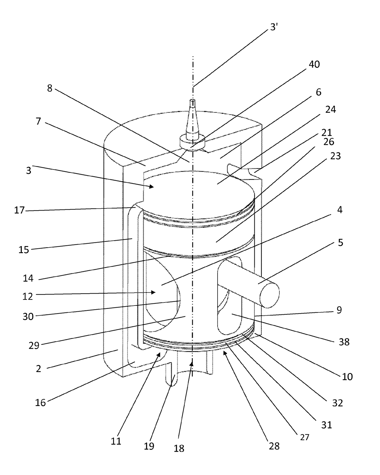
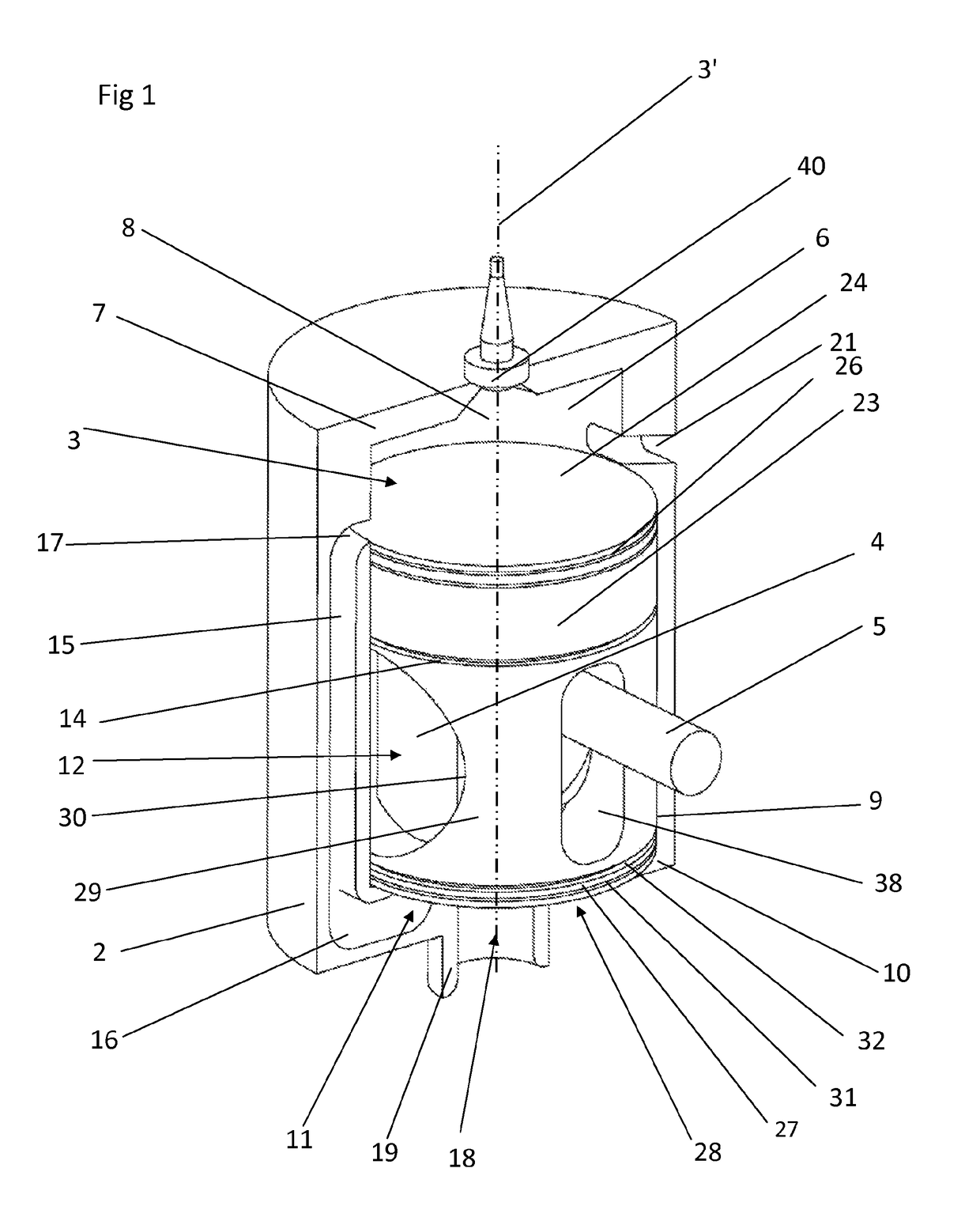
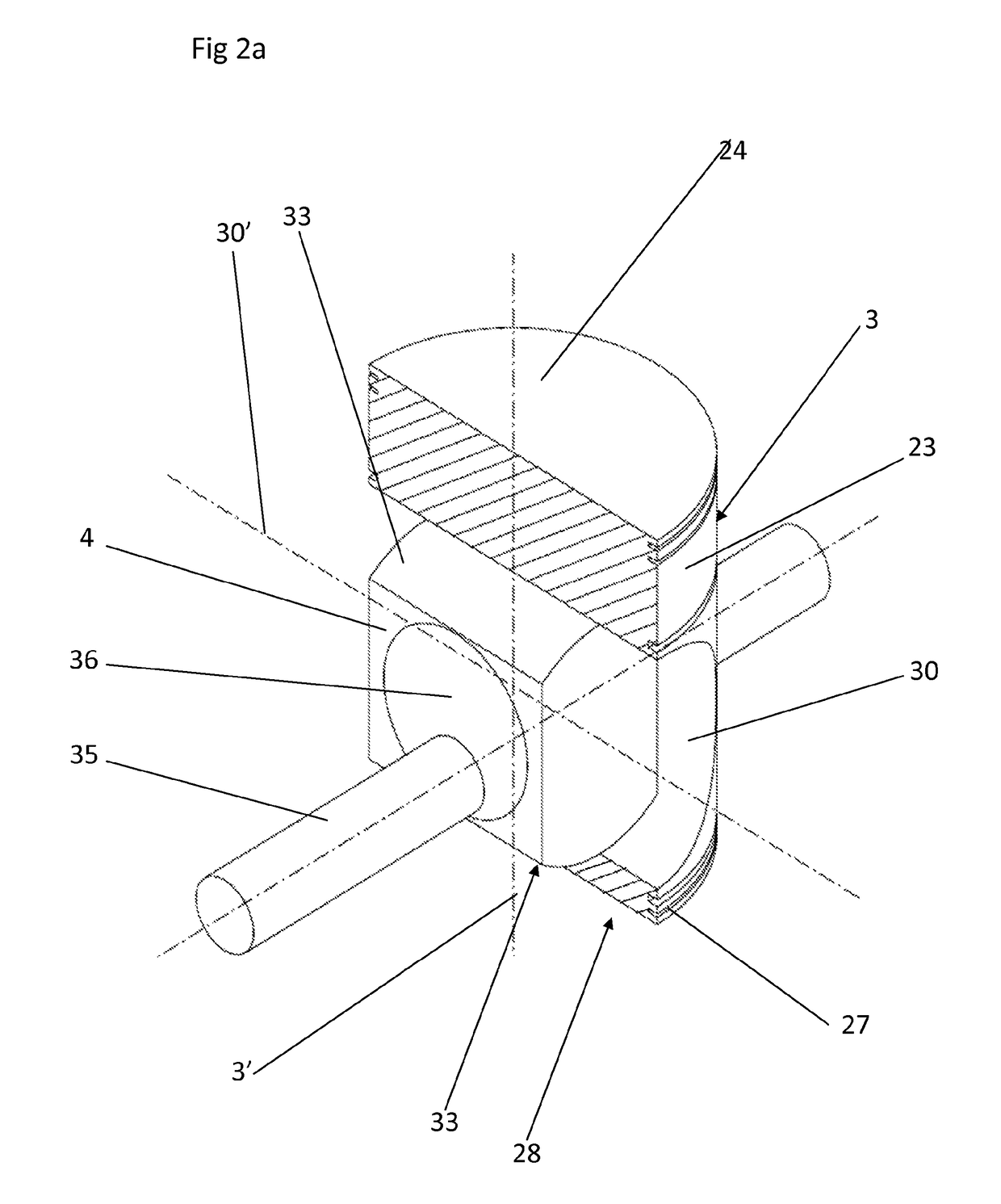
[0048]FIG. 1 shows a single cylinder, spark ignition two-stroke engine 1 according to one embodiment of the invention. The engine is shown and described in one possible orientation, however it is envisaged that the engine may be operated at any angle and the terms upper, lower and base etc. should be construed accordingly. The engine 1 includes a casing 2 (shown in partial cut-away in FIG. 1) and a piston 3 which is movable within the casing 2 in reciprocating motion in the direction of its axis 3′. The engine has a linear-to-rotary power transfer mechanism coupled to the piston including a shuttle bearing 4 and a camshaft 5. The power transfer mechanism is shown in more detail in FIGS. 2 to 5.

[0049]The casing 2 includes a first bore 6 and an upper wall 7 defining in part a working cylinder or combustion chamber 8. The casing 2 further includes a second bore 9 and a base wall 10 defining in part a supercharging cylinder or supercharging chamber 11. An intermediate chamber 12 is def...


PUM


Abstract

A piston arrangement comprising: a piston, a first chamber, a second chamber and a power transfer assembly; wherein the piston comprises a first head movable within the first chamber and a second head movable within the second chamber; wherein, in operation, the piston follows a linear path in reciprocating motion along a first axis; wherein the power transfer assembly comprises a shaft rotatably coupled to a shuttle bearing and arranged to convert the reciprocating motion of the piston to rotary motion of the shaft; wherein the shuttle bearing moves relative to the piston in reciprocating motion along a second axis substantially transverse to the first axis; and wherein the shuttle bearing is coupled to the piston via a non-planar bearing surface thereby allowing rotation of the shuttle bearing.

Description

[0001]The present application is a submission under 35 USC §371 of international application no. PCT / GB2013 / 051677, filed on 25 Jun. 2013 and published in the English language with publication no. WO 2014 / 001788 A1 on 3 Jan. 2014, which claims the benefit of the filing date of GB 1211490.6 filed 28 Jun. 2012.FIELD OF THE INVENTION[0002]The invention relates to a piston arrangement and to an internal combustion engine.BACKGROUND OF THE INVENTION[0003]Conventional internal combustion engines operating on either a two-stroke or a four-stroke cycle commonly use a crankshaft and con rod arrangement to convert linear motion of a piston to rotary motion at an output shaft. Due to the crankshaft and con rod geometry, maximum piston acceleration generally occurs when the piston is at top dead centre (TDC), where piston acceleration is significantly greater than at bottom dead centre (BDC).[0004]High piston acceleration at TDC poses several problems for engine performance. For example, in a s...

Claims


Application Information

Patent Timeline
Patent Type & Authority Patents(United States)
IPC IPC(8): F01B9/06F02F3/28F16J1/10F02B75/32F01B9/02F01B7/16
CPCF02F3/28F01B7/16F01B9/023F02B75/32F16J1/10F02M35/10157F01B9/02Y02T10/12F02B75/02F02B2075/025F02B2075/027F16C31/02F16C2360/22
Inventor JUKES, OLIVER
Owner OXFORD TWO STROKE
Why Eureka
Try Eureka