EUV light source with spectral purity filter and power recycling

a technology of spectral purity filter and light source, applied in the field of radiation generation, can solve the problems of not achieving the full rejection of all out-of-band radiation, not fully excluding other wavelengths, and affecting the lithography process, and achieve the effect of optimizing the diffraction efficiency of in-band wavelengths

Inactive Publication Date: 2017-04-04
JOHNSON KENNETH C
View PDF15 Cites 18 Cited by
  • Summary
  • Abstract
  • Description
  • Claims
  • Application Information

AI Technical Summary

Benefits of technology

[0047]The diffraction grating can be constructed as a substrate having a phase-Fresnel surface-relief structure, and a multilayer, reflective film stack deposited conformally on the phase-Fresnel structure. This type of grating will be termed “conformal-multilayer”. Alternatively, the grating can be constructed as a smooth substrate on which a multilayer, reflective film stack is deposited, with a phase-Fresnel surface-relief structure patterned in the film stack. This type of grating will be termed “patterned-multilayer”. In either case, the grating is blazed for optimal diffraction efficiency of the in-band wavelengths, and the grating has a sufficiently short period to achieve separatio

Problems solved by technology

But the mirror also reflects a large amount of plasma-generated “out-of-band” radiation from the deep ultraviolet (DUV) to long-wave infrared (IR), which can be detrimental to lithography processes.
A limitation of these types of systems is that they are generally designed to only extinguish the zero order at only one wavelength (10.6 μm), so they do not achieve full rejection of all out-of-band radiation.
But it does not fully exclude other wavelengths, including the DUV spectrum.
A drawback of the Moriya et al. design is that it requires many layers in the reflective film.
. . it is not possible sufficiently to separate the EUV radiation from the radiation of other wavelengths.”
A disadvantage of this type of grating is that it requires a very large number of Mo/Si bilayers (“at least two thousand” as recited in Chapman's claim 1).
Two disadvantages of this type of system are that it requires a separate optical element for spectral filtering, and the additional element significantly reduces EUV t

Method used


Image

  • EUV light source with spectral purity filter and power recycling
  • EUV light source with spectral purity filter and power recycling
  • EUV light source with spectral purity filter and power recycling

Examples


Embodiment Construction

Spectral Filtering

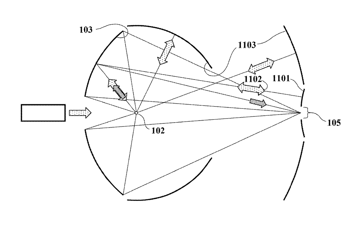
[0065]FIG. 6 and the enlarged view in FIG. 7 illustrate the spectral filtering function. A diffraction grating 701 on the collection mirror 103 is used to separate in-band and out-of-band radiation. The mirror does not focus undiffracted (zero-order) radiation from the plasma onto the IF 104 as in the prior-art system of FIG. 2; instead the zero-order reflection is directed outside of the IF aperture 105. The grating is not constructed primarily to diffractively scatter IR radiation out of the IF aperture; it is rather designed to efficiently diffract in-band EUV radiation into the aperture.

[0066]Some out-of-band radiation may be diffractively scattered by the grating, but the spectral filtering mechanism eliminates out-of-band radiation whether or not it is diffracted. The mechanism's operational principle is based on the grating's chromatic dispersion; it does not rely on zero-order extinction.

[0067]In the FIG. 6 embodiment, the mirror and grating are axially sym...


PUM


Abstract

A plasma-generated EUV light source uses an EUV-diffracting collection mirror to channel spectrally pure in-band radiation through an intermediate-focus aperture and through EUV illumination optics. Out-of-band radiation is either undiffracted by the collection mirror or is diffractively scattered away from the aperture. The undiffracted portion, plus plasma-emitted radiation that does not intercept the collection mirror, can be efficiently recycled back to the plasma via retroreflecting mirrors, cat's-eye reflectors, or corner-cube reflectors, to enhance generation of in-band EUV radiation by the plasma.

Description

CROSS-REFERENCE TO RELATED APPLICATIONS[0001]This application is a continuation application of PCT / US2016 / 034172, filed Jun. 24, 2016, entitled “EUV Light Source with Spectral Purity Filter and Power Recycling,” which claims the benefit under 35 U.S.C. §119(e) of the following six applications:[0002]U.S. Provisional Patent Application No. 62 / 265,992, filed Dec. 11, 2015 for “EUV Spectral Purity Filter for Full IR-to-VUV Out-of-Band Rejection, with IR Power Recycling”;[0003]U.S. Provisional Patent Application No. 62 / 273,598, filed Dec. 31, 2015 for “EUV Plasma Source with IR Power Recycling”;[0004]U.S. Provisional Patent Application No. 62 / 275,243, filed Jan. 6, 2016 for “EUV Plasma Source with IR Power Recycling”;[0005]U.S. Provisional Patent Application No. 62 / 279,753, filed Jan. 16, 2016 for “EUV Spectral Purity Filter for Full IR-to-VUV Out-of-Band Rejection, With IR Power Recycling”;[0006]U.S. Provisional Patent Application No. 62 / 281,478, filed Jan. 21, 2016 for “EUV Spectral P...

Claims


Application Information

Patent Timeline
IPC IPC(8): A61N5/00G02B19/00H05G2/00G02B5/18G03B27/72G03B27/54G03F7/20G03B27/32
CPCG02B5/1838H05G2/008G02B19/0095G03F7/70033G03F7/70175G03F7/70158G02B5/122G03F7/7015G03F7/70191G03F7/70575G21K1/062G21K1/067G21K2201/064
Inventor JOHNSON, KENNETH C.
Owner JOHNSON KENNETH C
Why Eureka
Try Eureka