
Composite substrate manufacturing method, and composite substrate

a manufacturing method and composite substrate technology, applied in the direction of basic electric elements, electrical apparatus, semiconductor devices, etc., can solve the problems of difficult bonding of surface to bondable level, high cost of single-crystal materials, and defect in semiconductor materials, so as to reduce surface roughness, good insulating properties, and easy bonding

Active Publication Date: 2017-04-04
SHIN ETSU CHEM IND CO LTD
View PDF22 Cites 2 Cited by
  • Summary
  • Abstract
  • Description
  • Claims
  • Application Information

AI Technical Summary

Benefits of technology

The invention allows for the creation of a coating with good insulating properties that can be easily bonded to a support substrate. This results in a smooth surface that is suitable for use in electronic devices. The insulating film can be attached without needing to be polished or treated in any other way. This makes the process simpler and more efficient.

Problems solved by technology

Defects in these semiconductor materials become a problem to be overcome prior to practical implementation.
However, these single-crystal materials are expensive.
However, in the case of GaN wafer and SiC wafer, for example, it is very difficult to smoothen their surface to the bondable level or such smoothening needs a cost.
As in the case of bonding of GaN wafer or SiC wafer, when a polycrystalline material or a suitable substrate having a polycrystalline material deposited on its surface is bonded to a substrate of different species, direct bonding is impossible because the polycrystalline material has a substantially irregular surface.
However, these methods suffer from problems of an expensive equipment and cost needed for deposition.
Extra steps cause another problem to the process.
Since the SOG material contains impurities such as B, P and Na, it is difficult to use the material as a joint layer in electronic device applications using SOI, SOS, SiC, GaN or the like.
As discussed above, the formation of amorphous material by CVD technique is one known example of the means for providing a smooth bonding layer on a substrate surface having a considerable roughness, but suffers from the problem of cost because an expensive equipment is necessary for film deposition, and polishing must be carried out for smoothening after the film deposition.
However, since bonding follows polishing, it has not been studied whether or not a SiO2 film reduces the roughness of a bonding surface to enable bonding without a need for polishing, and whether or not the resulting SiO2 film is at a film quality level ready for use at the electronic device joint surface as the insulating film.

Method used


Image

  • Composite substrate manufacturing method, and composite substrate
  • Composite substrate manufacturing method, and composite substrate
  • Composite substrate manufacturing method, and composite substrate

Examples


example 1

[0066]A test sample was prepared and evaluated by the following procedure.

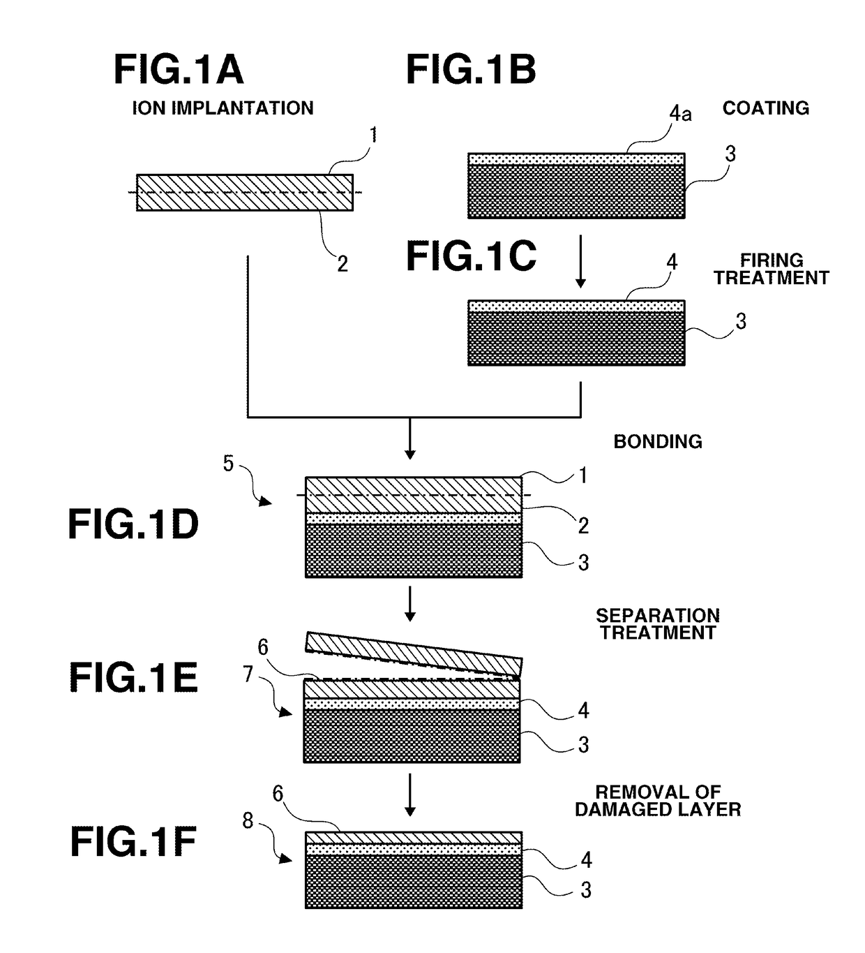
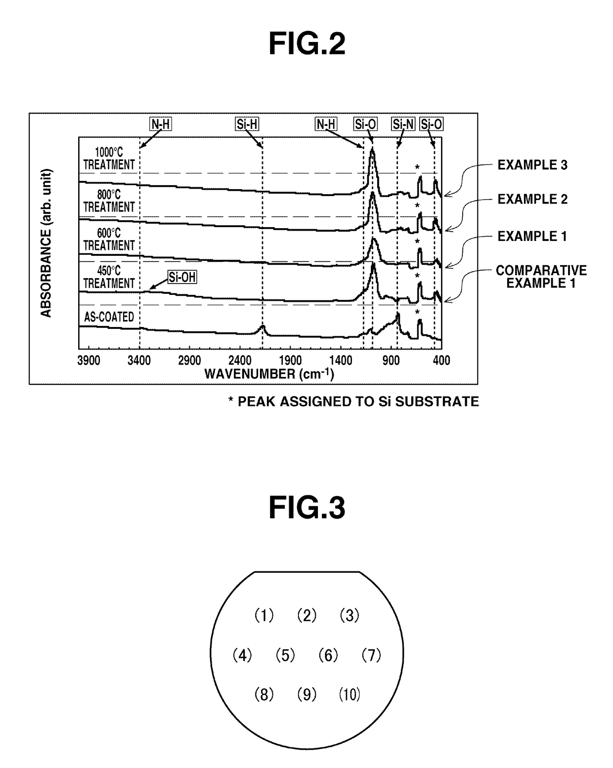
[0067]First, a film was formed by conversion from perhydropolysilazane to SiO2 on a support substrate in the form of Si wafer. Specifically, 2 mL of a solution containing 20 wt % perhydropolysilazane in di-n-butyl ether solvent (Tresmile, Product No. ANN120-20 by Sanwa Kagaku Corp.) was spin coated onto a Si wafer with an outer diameter of 150 mm, and then heated at 150° C. for 3 minutes to remove the solvent. Then firing treatment was carried out by heating in air at 600° C. for 3 minutes, for converting the coating to a SiO2 film. The film at the end of firing treatment had a thickness of 200 nm. A change in quality of the film before and after the firing treatment was confirmed by IR absorption spectroscopy, and the SiO2 film surface after the firing treatment was measured for surface roughness (Rms) under an atomic force microscope (AFM). Further, the SiO2 film was evaluated for dielectric strength at 10 p...

example 2

[0070]The same procedure as in Example 1 was repeated except that the firing temperature was changed to 800° C., thereby transferring a Si single crystal thin film to the support substrate. It was evaluated as in Example 1.

example 3

[0071]The same procedure as in Example 1 was repeated except that the firing temperature was changed to 1,000° C., thereby transferring a Si single crystal thin film to the support substrate. It was evaluated as in Example 1.


PUM

PropertyMeasurementUnit
surface roughness Rmsaaaaaaaaaa
heightaaaaaaaaaa
temperatureaaaaaaaaaa

Abstract

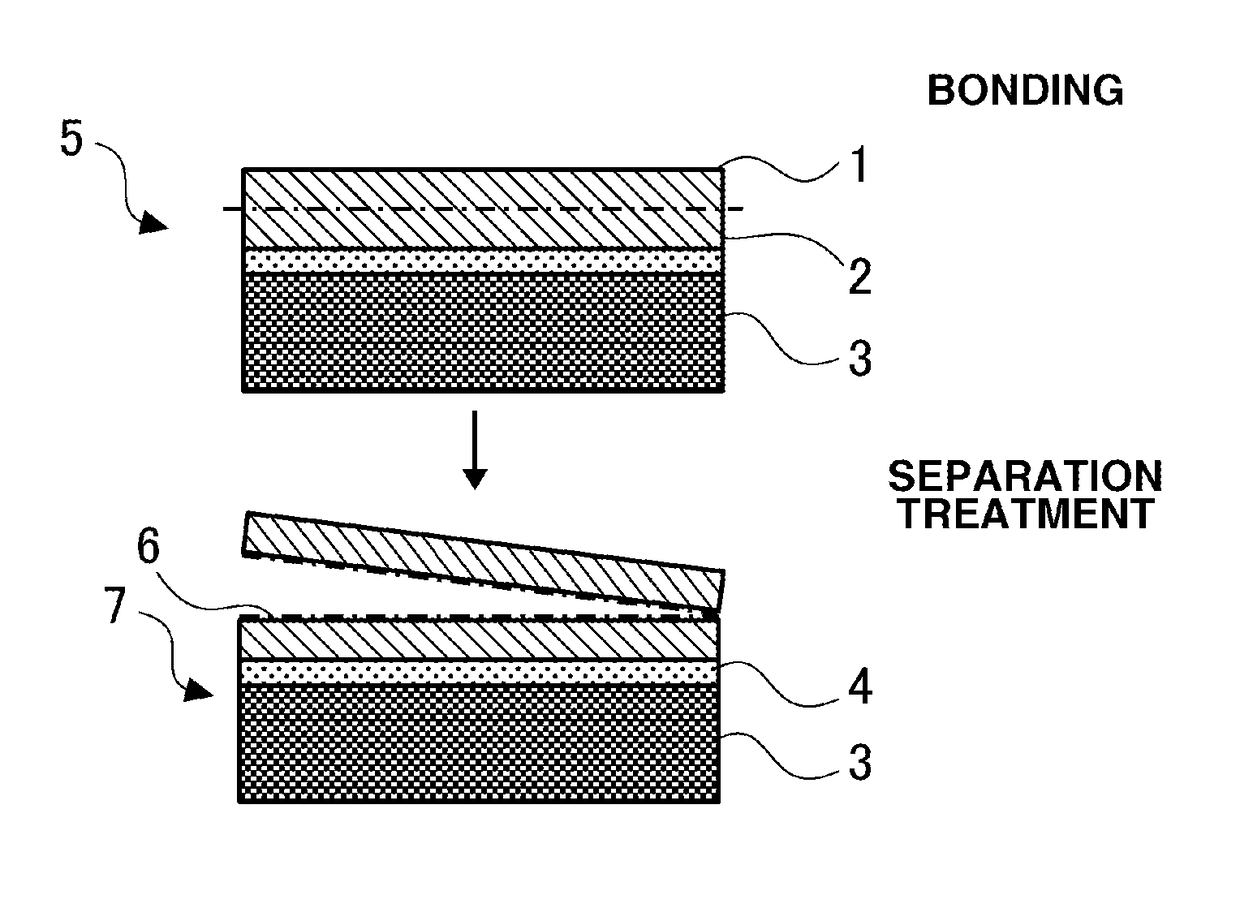
Disclosed is a composite substrate manufacturing method whereby, after bonding a semiconductor substrate (1) and a supporting substrate (3) to each other, the semiconductor substrate (1) is thinned, and a composite substrate (8) having a semiconductor layer (6) on the supporting substrate (3) is obtained. On the supporting substrate (3) surface to be bonded, a coating film (4a) containing polysilazane is formed, a silicon-containing insulating film (4) is formed by performing firing by heating the coating film (4a) to 600-1,200° C., then, the semiconductor substrate (1) and the supporting substrate (3) are bonded to each other with the insulating film (4) therebetween, thereby suppressing bonding failures due to surface roughness and defects of the supporting substrate, and easily obtaining the composite substrate.

Description

TECHNICAL FIELD[0001]This invention relates to a method for preparing a composite substrate by the step of bonding a semiconductor substrate to a support substrate via an insulating film, and a composite substrate obtained by the method.BACKGROUND ART[0002]Studies are made to apply Group III-V semiconductors such as GaN and wide-gap semiconductors such as SiC to light-emitting elements, high-breakdown-voltage devices and RF devices by utilizing their own physical properties. Defects in these semiconductor materials become a problem to be overcome prior to practical implementation. For the purpose of reducing defects in a material, use of single-crystal bulk materials is more advantageous than the heteroepitaxial growth of thin film as long as the number of defects is concerned. However, these single-crystal materials are expensive. The preparation method via ion implantation / separation is employed in the manufacture of silicon-on-insulator (SOI) or silicon-on-sapphire (SOS), for exa...

Claims


Application Information

Patent Timeline
Patent Type & Authority Patents(United States)
IPC IPC(8): H01L21/46H01L21/302H01L29/06H01L21/265H01L21/02H01L21/762H01L21/683
CPCH01L21/76254H01L21/02164H01L21/02222H01L21/02282H01L21/02326H01L21/02329H01L21/02337H01L21/265H01L21/302H01L21/6835H01L29/0649H01L2221/68327
Inventor KONISHI, SHIGERUSHIRAI, SHOZO
Owner SHIN ETSU CHEM IND CO LTD
Learn More