Radiation imaging apparatus and radiation imaging system

a radiation imaging and radiation imaging technology, applied in the field of radiation imaging apparatus and radiation imaging system, can solve the problems of unexpected radiation dose, high initial cost, and low detection efficiency, and achieve the effect of reducing power consumption and shortening the time required for radiation detection

Active Publication Date: 2017-05-23
CANON KK
View PDF9 Cites 31 Cited by
  • Summary
  • Abstract
  • Description
  • Claims
  • Application Information

AI Technical Summary

Benefits of technology

[0012]The present invention provides a radiation imaging apparatus and a radiation imaging system, which are capable of reducing power consumption or cutting short the time required to detect radiation.

Problems solved by technology

The introduction cost is therefore problematically high.
However, a preset amplification ratio may not work depending on the performance of the radiation imaging apparatus and the positional relation between a subject and the radiation imaging apparatus.
Specifically, there are cases where the positional relation of a subject with the radiation imaging apparatus makes the dose of the incident radiation ray unexpectedly large and where a radiation ray transmitted through a thick subject falls farther short of the radiation imaging apparatus than expected.
In such cases, the excessively large dose or the excessively small dose can degrade image quality in an area that needs diagnosis most (an interested area).
However, the radiation detecting apparatus of Japanese Patent Application Laid-Open No. 2004-85383, where signals of the X-ray irradiation amount detecting pixels are read out by a shared readout circuit, which reads out signals of the image forming pixels as well, has the following problems:
The first problem is power consumption.
Detecting X-ray irradiation involves constant readout of the X-ray irradiation amount detecting pixels, which means that a huge amount of power is consumed to obtain one X-ray image.
An increase in power consumption gives rise to problems such as limitations put on the length of drive time by heat generation of equipment, and a shortened drive time in a battery-driven radiation imaging apparatus.
The second problem is the time required to output data.
In the case of the short irradiation of an intense X-ray, lengthy readout of the detecting pixels means that the right X-ray dose has been exceeded by the time a control circuit determines that there has been X-ray irradiation, and therefore hinders proper control by AEC.

Method used


Image

  • Radiation imaging apparatus and radiation imaging system
  • Radiation imaging apparatus and radiation imaging system
  • Radiation imaging apparatus and radiation imaging system

Examples


first embodiment

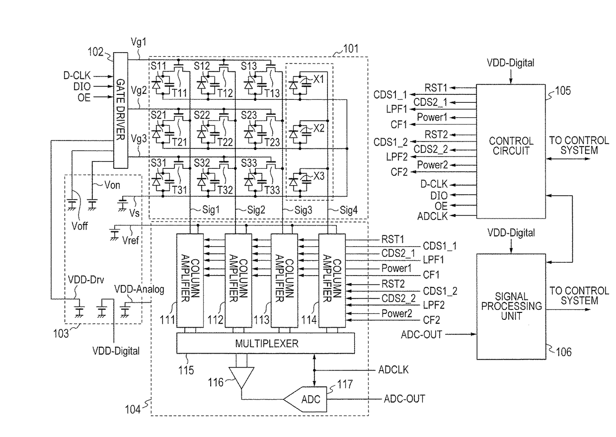
[0023]FIG. 1 is a diagram for illustrating a configuration example of a radiation imaging apparatus according to a first embodiment of the present invention. An area sensor 101 includes first conversion elements S11 to S33, second conversion elements X1 to X3, and TFT switches T11 to T33. The first conversion elements S11 to S33 and the TFT switches T11 to T33 are included in a plurality of image pixels for obtaining a radiographic image. The second conversion elements X1 to X3 are included in a plurality of radiation detecting pixels for detecting radiation irradiation in order to monitor the radiation irradiation amount, or the like. The conversion elements S11 to S33 and X1 to X3 are arranged so as to together form a matrix pattern. The conversion elements S11 to S33 and X1 to X3 convert a radiation ray (for example, X-ray) into electric charge. For instance, the conversion elements S11 to S33 and X1 to X3 each include a wavelength conversion member, which is made of GOS or CsI a...

second embodiment

[0062]FIG. 5 is a diagram for illustrating a configuration example of a radiation imaging system according to a second embodiment of the present invention. The radiation imaging system of this embodiment includes, in addition to the radiation imaging apparatus 501 of the first embodiment, a wireless communication unit 504, the control system 505, and the radiation generating apparatus 509. The radiation imaging apparatus 501 includes the area sensor 101, the gate driver 102, the power circuit 103, the readout circuit 104, the control circuit 105, and the signal processing unit 106 as in FIG. 1, and further includes a battery 502 and a wireless communication unit 503. The battery 502 supplies a supply voltage to the power circuit 103. The control circuit 105 and the signal processing unit 106 hold communication to and from the wireless communication unit 504 via the wireless communication unit 503.

[0063]The control system 505 includes a computer 506, a wireless communication device 5...

third embodiment

[0066]FIG. 6 is a diagram for illustrating a configuration example of a radiation imaging apparatus according to a third embodiment of the present invention. This embodiment (FIG. 6) is obtained by adding a switching unit 601 and a timing generator 602 to the first embodiment (FIG. 1). Differences of this embodiment from the first embodiment are described below.

[0067]The second conversion element X1 of the radiation detecting pixels is connected to the column amplifier 111 via the signal line Sig1. The first conversion elements S21 and S31 of the image pixels are connected to the column amplifier 112 via the signal line Sig2. The first conversion elements S12, S22, and S32 of the image pixels are connected to the column amplifier 113 via the signal line Sig3. The first conversion elements S13, S23, and S33 of the image pixels are connected to the column amplifier 114 via the signal line Sig4.

[0068]The switching unit 601 supplies the column amplifiers 111 to 114 with the control sign...


PUM


Abstract

Provided is a radiation imaging apparatus, including: a first conversion element arranged to convert a radiation ray into electric charge in order to obtain a radiographic image; a first amplifier arranged to output a voltage corresponding to the electric charge of the first conversion element; a second conversion element arranged to convert the radiation ray into electric charge in order to detect radiation irradiation; a second amplifier arranged to output a voltage corresponding to the electric charge of the second conversion element; and a control circuit configured to control the first amplifier and the second amplifier, in which the control circuit is capable of controlling the second amplifier independently of control that is exerted over the first amplifier.

Description

BACKGROUND OF THE INVENTION[0001]Field of the Invention[0002]The present invention relates to a radiation imaging apparatus and a radiation imaging system.[0003]Description of the Related Art[0004]In medical and other fields, there have been put into practical use radiation imaging apparatuses, which are configured to receive irradiation of a radiation ray or the like after being transmitted through a subject, hold image signals of the subject's image, and output electric charge signals that reflect the held radiographic image. As an example of the radiation imaging apparatuses, there is given one that is configured to combine a photo sensor with a semiconductor material or a fluorescent substance that generates electric charge in an amount determined by the amount of radiation irradiating the apparatus. This radiation imaging apparatus has an area sensor unit, which includes thin film transistor (TFT) switches and photoelectric conversion elements. The TFT switches are formed mainl...

Claims


Application Information

Patent Timeline
Patent Type & Authority Patents(United States)
IPC IPC(8): H05G1/56A61B6/00G01T1/17H03F3/45H03F3/70H04N5/32H04N5/355H04N5/378
CPCA61B6/585A61B6/4266G01T1/17H03F3/45475H03F3/70H04N5/32H04N5/355H04N5/378H03F2203/45514H03F2203/45634H04N25/57H04N25/75
Inventor YAGI, TOMOYUKIKAMESHIMA, TOSHIOTAKENAKA, KATSUROIWASHITA, ATSUSHISATO, ERIKOOKADA, HIDEYUKIRYU, TAKUYATERUI, KOSUKE
Owner CANON KK
Why Eureka
Try Eureka