Method of making photonic crystal
a technology of photonic crystals and materials, applied in the direction of single crystal growth, polycrystalline material growth, chemistry apparatus and processes, etc., can solve the problems of imposing limitations on the choice of materials for photonic crystals, and achieve the effects of increasing the photonic band gap, and increasing the refractive index differen
- Summary
- Abstract
- Description
- Claims
- Application Information
AI Technical Summary
Benefits of technology
Problems solved by technology
Method used
Image
Examples
embodiment 1
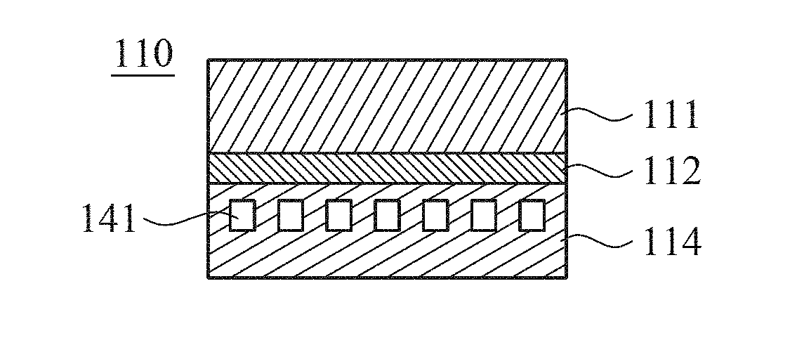
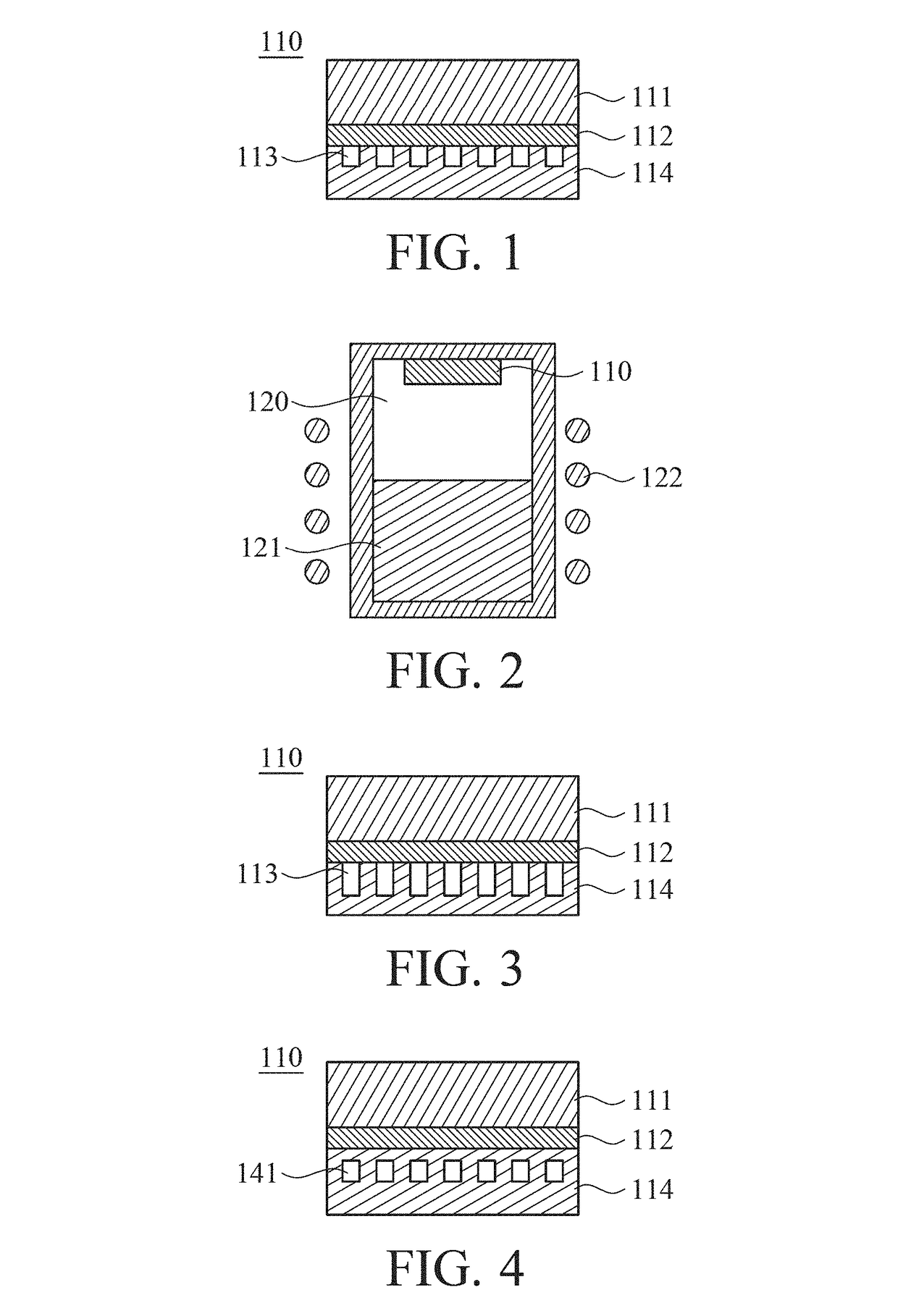
[0040]Embodiment 1 is implemented by following the steps below to make a photonic crystal having a single layer of submicron voids.
[0041]Step 1: providing a seed, followed by etching a surface of the seed to form thereon submicron voids.
[0042]In embodiment 1, the seed is silicon carbide, but the present invention is not limited thereto. The seed can also be any other wide-bandgap material, such as aluminum nitride or gallium nitride. Preferably, the seed has a silicon surface whenever silicon carbide serves as the seed.
[0043]In step 1, a surface of the seed is etched to thereby take on a submicron pattern formed from submicron voids.
[0044]In step 1, the submicron voids have a depth of 500 μm, but the present invention is not limited thereto. Preferably, the submicron voids have a depth of 500 μm or more.
[0045]Step 2: providing a graphite disk, followed by coating one side of the graphite disk with a graphite adhesive whereby the void-formed surface of the seed is attached to the gra...
embodiment 2
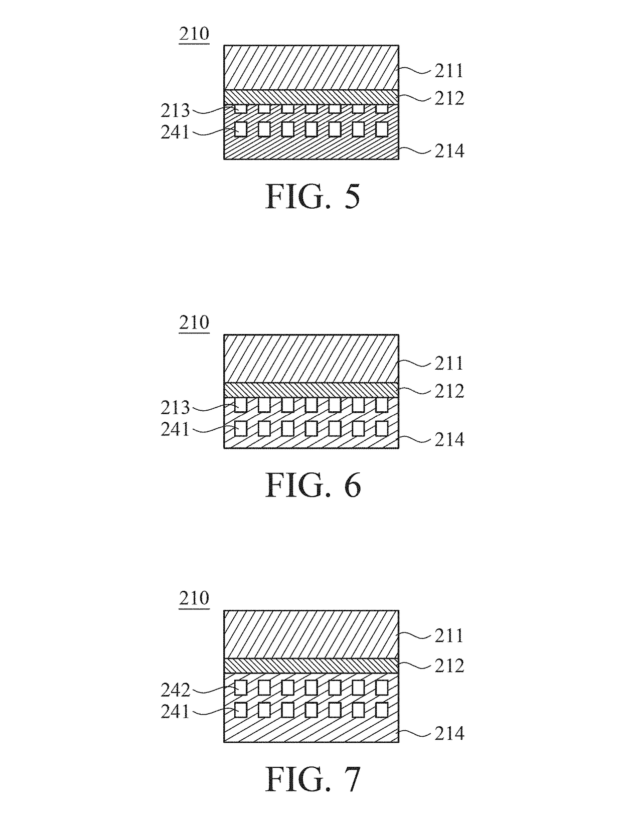
[0055]In embodiment 2, a photonic crystal with two layers of submicron voids is made by following the steps below.
[0056]Step 1: a photonic crystal made in embodiment 1 is provided to serve as a seed, and then one surface of the seed is etched to form a seed with a surface having submicron voids.
[0057]In embodiment 2, the seed is silicon carbide, but the present invention is not limited thereto. The seed can also be any other wide-bandgap material, such as aluminum nitride or gallium nitride. In the situation where silicon carbide is used as a seed, the seed has a silicon surface, preferably.
[0058]In step 1, a surface of the seed is etched to thereby take on a submicron pattern formed from submicron voids.
[0059]In step 1, the submicron voids have a depth of 500 μm, but the present invention is not limited thereto. Preferably, the submicron voids have a depth of 500 μm or more.
[0060]Step 2: providing a graphite disk, followed by coating one side of the graphite disk with a graphite ad...
embodiment 3
[0071]In embodiment 3, a photonic crystal with one layer of submicron voids each enclosing a doping element is made by following the steps below.
[0072]Step 1: providing a seed, followed by etching a surface of the seed to form thereon submicron voids.
[0073]In embodiment 3, the seed is silicon carbide, but the present invention is not limited thereto. The seed can also be made from any other wide-bandgap material, such as aluminum nitride or gallium nitride. In the situation where the seed is made from silicon carbide, the seed has a silicon surface, preferably.
[0074]In step 1, a surface of the seed is etched to thereby take on a submicron pattern formed from submicron voids.
[0075]In step 1, the submicron voids have a depth of 500 μm, but the present invention is not limited thereto. Preferably, the submicron voids have a depth of 500 μm or more.
[0076]Step 2: providing a graphite disk, followed by coating one side of the graphite disk with a graphite adhesive whereby the void-formed ...
PUM
| Property | Measurement | Unit |
|---|---|---|
| depth | aaaaa | aaaaa |
| refractive index | aaaaa | aaaaa |
| refractive index | aaaaa | aaaaa |
Abstract
Description
Claims
Application Information
 - R&D
- Intellectual Property
- Life Sciences
- Materials
- Tech Scout
- Unparalleled Data Quality
- Higher Quality Content
- 60% Fewer Hallucinations
Browse by: Latest US Patents, China's latest patents, Technical Efficacy Thesaurus, Application Domain, Technology Topic, Popular Technical Reports.
© 2025 PatSnap. All rights reserved.Legal|Privacy policy|Modern Slavery Act Transparency Statement|Sitemap|About US| Contact US: help@patsnap.com


