Process for producing a syngas intermediate suitable for the production of hydrogen

a technology of syngas and intermediates, applied in the field of process for the production of syngas, can solve the problems of metal dusting, a catastrophic form of corrosion, and shorten and achieve the effect of shortening the life of the equipment involved

Active Publication Date: 2017-07-11
STAMICARBON ACTING UNDER THE NAME OF MT INNOVATION CENT
View PDF17 Cites 4 Cited by
  • Summary
  • Abstract
  • Description
  • Claims
  • Application Information

AI Technical Summary

Problems solved by technology

At the outlet temperatures of the CPO a corrosion problem called “metal dusting.” may appear.
Metal dusting is a catastrophic form of corrosion that occurs when susceptible materials are exposed to environments with high carbon activities.
This may shorten the life of the equipment involved, and may lead to contamination problems in end-product obtained from such equipment.
However, it is practically difficult to design and operate the PGB for lower residence times because lower residence times lead to very high gas velocities which in turn may increase the material problems incurred.

Method used


Image

  • Process for producing a syngas intermediate suitable for the production of hydrogen
  • Process for producing a syngas intermediate suitable for the production of hydrogen
  • Process for producing a syngas intermediate suitable for the production of hydrogen

Examples


first embodiment

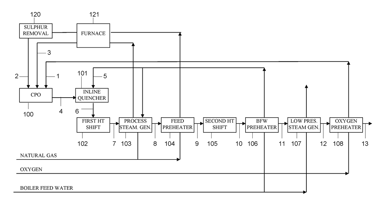
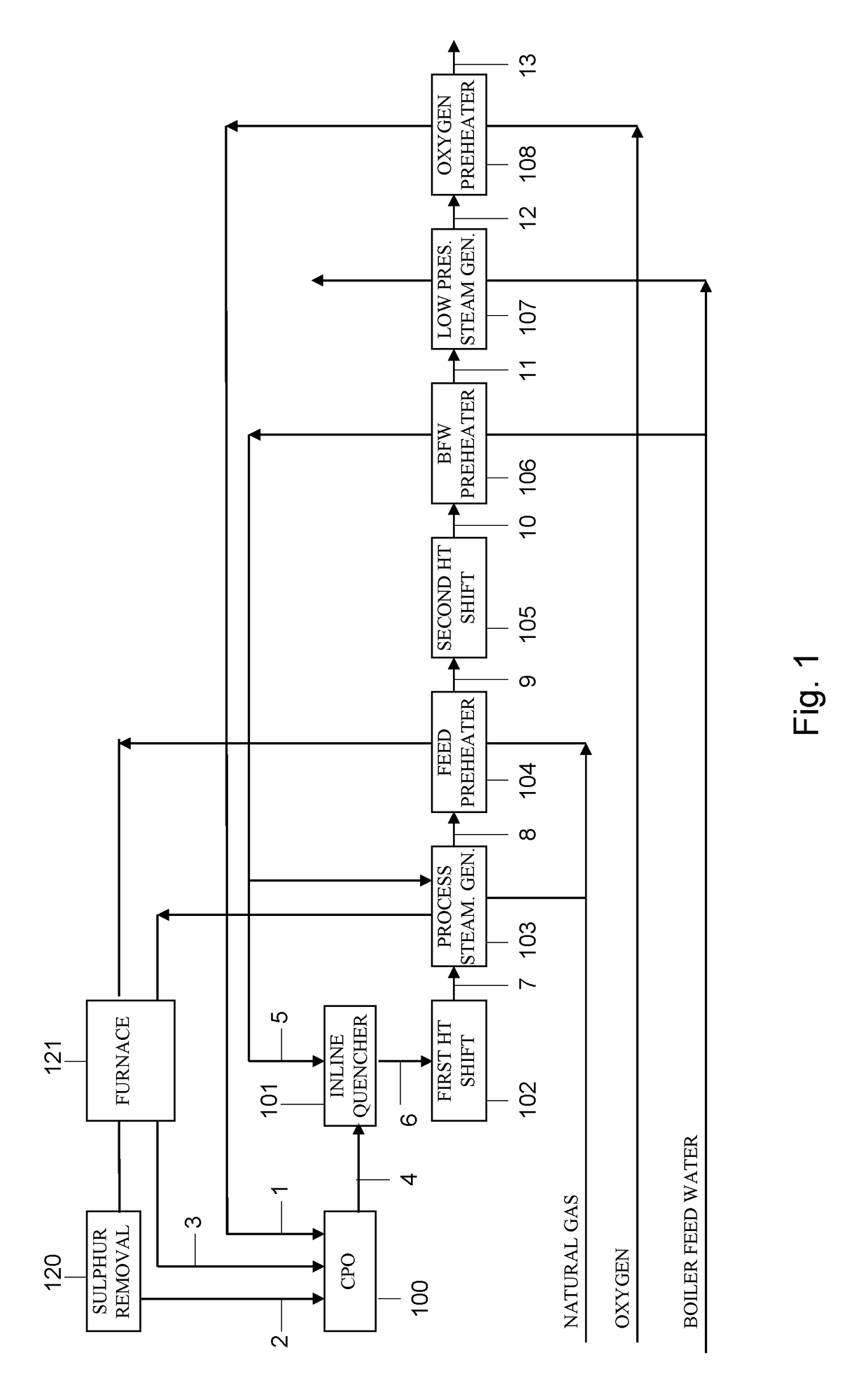
[0038]In FIG. 1, the present invention is illustrated in a schematic form.

[0039]FIG. 1 shows the block diagram of the process with the following sections:[0040]100, CPO section;[0041]101, quenching section;[0042]102, first HTS section;[0043]103, process steam generation section;[0044]104, feed preheater;[0045]105, second HTS section;[0046]106, BFW preheater section[0047]107, low pressure steam generation section[0048]108, oxygen preheater section;[0049]120, sulfur removal reactor;[0050]121, furnace.

[0051]To the syngas stream from CPO reactor, 100, water is added in 101 to cool the syngas temperature to 320-350° C. which represents a proper temperature to carry out the high temperature water gas shift reaction and which is outside the critical temperature range for metal dusting phenomenon. Unless indicated otherwise all percentages referred to are vol. %.

[0052]The synthesis gas exits the water quencher, 101, with a product containing about 32.7% of H2, 0.5% of unconverted CH4, 2.6% ...

second embodiment

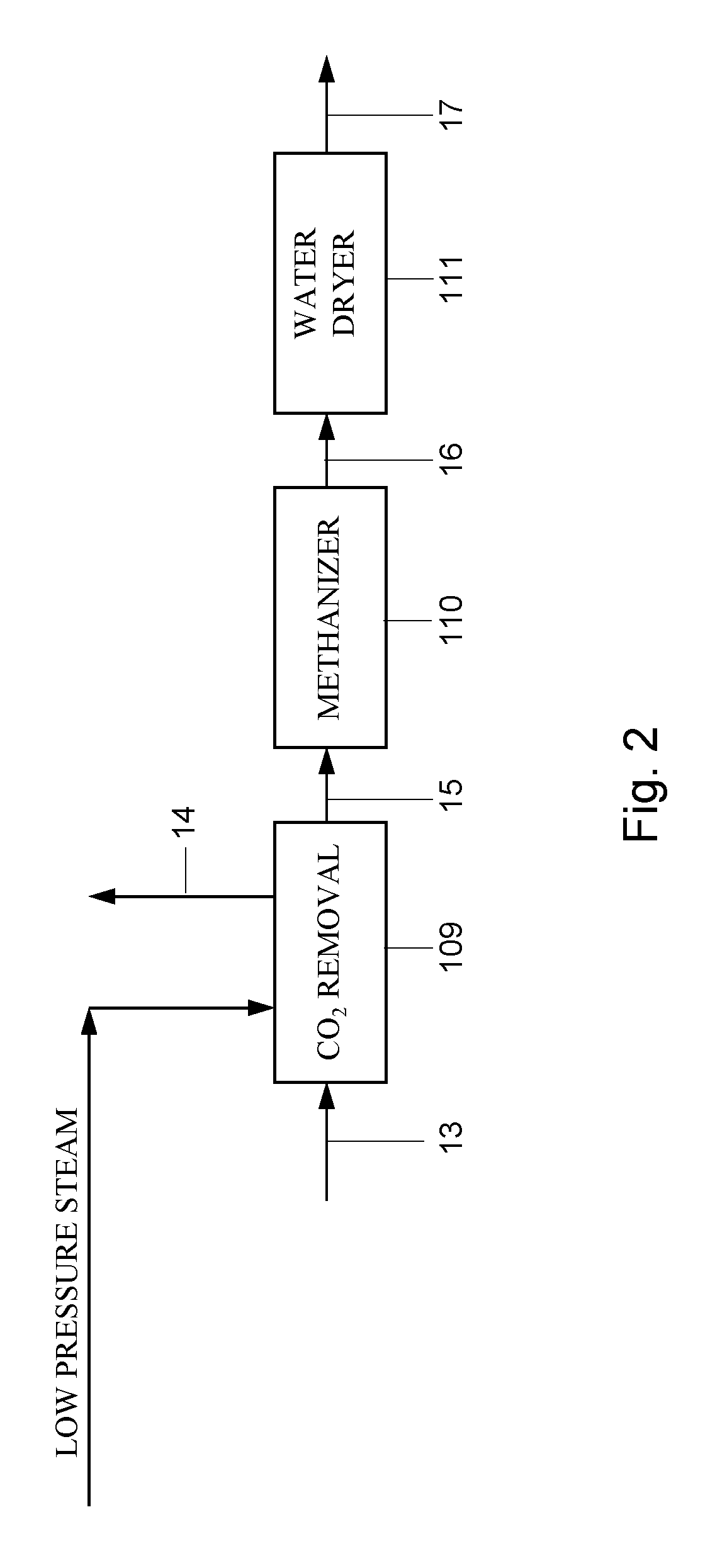
[0064]Referring now to FIG. 2, the present invention is illustrated in schematic form.

[0065]For simplicity, units and streams, FIG. 2 has in common with FIG. 1 have retained the unit or stream number of FIG. 1 so it shows only the following section.[0066]109, CO2 removal section;[0067]110, methanizer reactor section;[0068]111, water dryer section.

[0069]The shifted gas, 10, is processed in acid gas unit 109.

[0070]In acid gas stream, 13, the CO2 is separated from the syngas product. Stream 14 consists of CO2 removed.

[0071]The raw H2 stream, 15, is routed in reactor, 110, where CO is converted in CH4 and in reactor 111, where water is removed.

[0072]The H2 product, 17, has purity of 93.7% and can be used for applications which do not require high purity H2. If desired the H2 stream can be further purified with a pressure swing absorption (PSA) unit (not shown) or in case a CO2 separated stream is not required instead of steps 109, 110 or 111.

[0073]The above illustrated embodiments are i...


PUM

PropertyMeasurementUnit
temperatureaaaaaaaaaa
residence timeaaaaaaaaaa

Abstract

Disclosed is a process for the production of a syngas mixture by catalytic partial oxidation. The syngas mixture is suitable as an intermediate in the production of hydrogen. According to the invention, the syngas is cooled, prior to a water gas shift reaction, with liquid water. This has the advantage of avoiding the problem of metal dusting, and it presents a gas mixture comprising water vapor that is particularly suitable for a water gas shift reaction in the production of hydrogen.

Description

CROSS-REFERENCE TO RELATED APPLICATIONS[0001]This application is the national phase of PCT application PCT / NL2012 / 050443 having an international filing date of 25 Jun. 2012, which claims benefit of European application No. 11171172.7, filed 23 Jun. 2011. The contents of the above patent applications are incorporated by reference herein in their entirety.FIELD OF THE INVENTION[0002]The invention pertains to a process for the production of syngas by means of catalytic partial oxidation. In another aspect the invention relates to a method of making ammonia and / or urea using the syngas obtained by the process. In yet another aspect the method relates to a method for producing hydrogen.BACKGROUND OF THE INVENTION[0003]Syngas (which is a short for “synthesis gas”) comprises carbon monoxide (CO) and hydrogen (H2), and is an important source for the production of H2. The conventional industrial process for producing syngas on an industrial scale is steam reforming, whereby a carbonaceous ma...

Claims


Application Information

Patent Timeline
Patent Type & Authority Patents(United States)
IPC IPC(8): C01B3/26C01B3/38C01B3/48C07C273/04C01B3/50
CPCC01B3/26C01B3/386C01B3/48C01B3/50C07C273/04C01B2203/0261C01B2203/0475C01B2203/068C01B2203/0877C01B2203/1241
Inventor IAQUANIELLO, GAETANOCUCCHIELLA, BARBARAANTONETTI, ELENA
Owner STAMICARBON ACTING UNDER THE NAME OF MT INNOVATION CENT
Why Eureka
Try Eureka