
Method for manufacturing high strength flake graphite cast iron for an engine body and flake graphite cast iron for an engine body

a technology of flake graphite and cast iron, which is applied in the direction of machines/engines, mechanical equipment, casings, etc., can solve the problems of unavowable increase of material cost, high chill, and limited use of flake graphite cast iron for engine cylinder blocks and heads that require explosion pressures of more than 180 bar, etc., to achieve excellent processibility and fluidity, high strength, and high strength

Active Publication Date: 2017-07-18
DOOSAN INFRACORE CO LTD
View PDF14 Cites 0 Cited by
  • Summary
  • Abstract
  • Description
  • Claims
  • Application Information

AI Technical Summary

Benefits of technology

[0011]In order to solve the aforementioned problems, an embodiment of the present disclosure is to provide flake graphite cast iron which simultaneously has high strength and excellent processibility and fluidity even though ferroalloy such as molybdenum (Mo) or copper (Cu) is added to achieve high strength by controlling a content of strontium (Sr) among a very small amount of components added in cast iron and a content ratio between sulfur (S) and strontium (Sr) to be in a predetermined range, and a method for manufacturing the same.
[0012]An embodiment of the present disclosure is to also provide cast iron having a stable property and structure by precisely controlling a using ratio between sulfur and strontium, and more particularly, to provide flake graphite cast iron capable of being applied to an engine body for an internal combustion engine having a complicated shape, preferably, an engine cylinder block and / or an engine cylinder head.
[0026]As stated above, according to the present disclosure, since the content of the strontium (Sr) and the ratio (S / Sr) of the content of the sulfur (S) to the content of the strontium (Sr) are precisely controlled, it is possible to provide flake graphite cast iron which has a high tensile strength of 300 to 350 MPa and excellent processibility and fluidity even though ferroalloy such as Cu or Mo is added and is appropriately used for engine components of an internal combustion engine, and a method for manufacturing the same.

Problems solved by technology

However, since tensile strength is about 150 to 250 MPa, there is a limitation in using the flake graphite cast iron for the engine cylinder block and head requiring an explosion pressure of more than 180 bar.
However, since the addition of the ferroalloy may potentially cause the occurrence of the chill, there is a problem in that the chill is highly likely to be caused in thin walled parts of engine cylinder block and head having a complicated structure.
Thus, material cost may be unavodiably increased.
However, when a large quantity of manganese (Mn) is added, since carbide is stabilized to disturb growth of the graphite.
Therefore, there is a limitation in applying the flake graphite cast iron to the engine cylinder block and head having a complicated structure.
However, since it is difficult to control the magnesium (Mg) and the CGI is very sensitive to changes of melting and casting conditions such as a tapping temperature and a tapping speed, it is highly likely to cause material quality deterioration of the CGI and casting defect.
Further, manufacturing cost may be increased.
Moreover, since the CGI has relatively poor processibility than the flake graphite cast iron, when the engine cylinder block and head are manufactured using the CGI, it is difficult to manufacture the engine cylinder block and head in an existing processing line for the flake graphite cast iron, and it is necessary to change the processing line to a processing line for the CGI.
Accordingly, enormous facility investment cost may be incurred.

Method used


Image

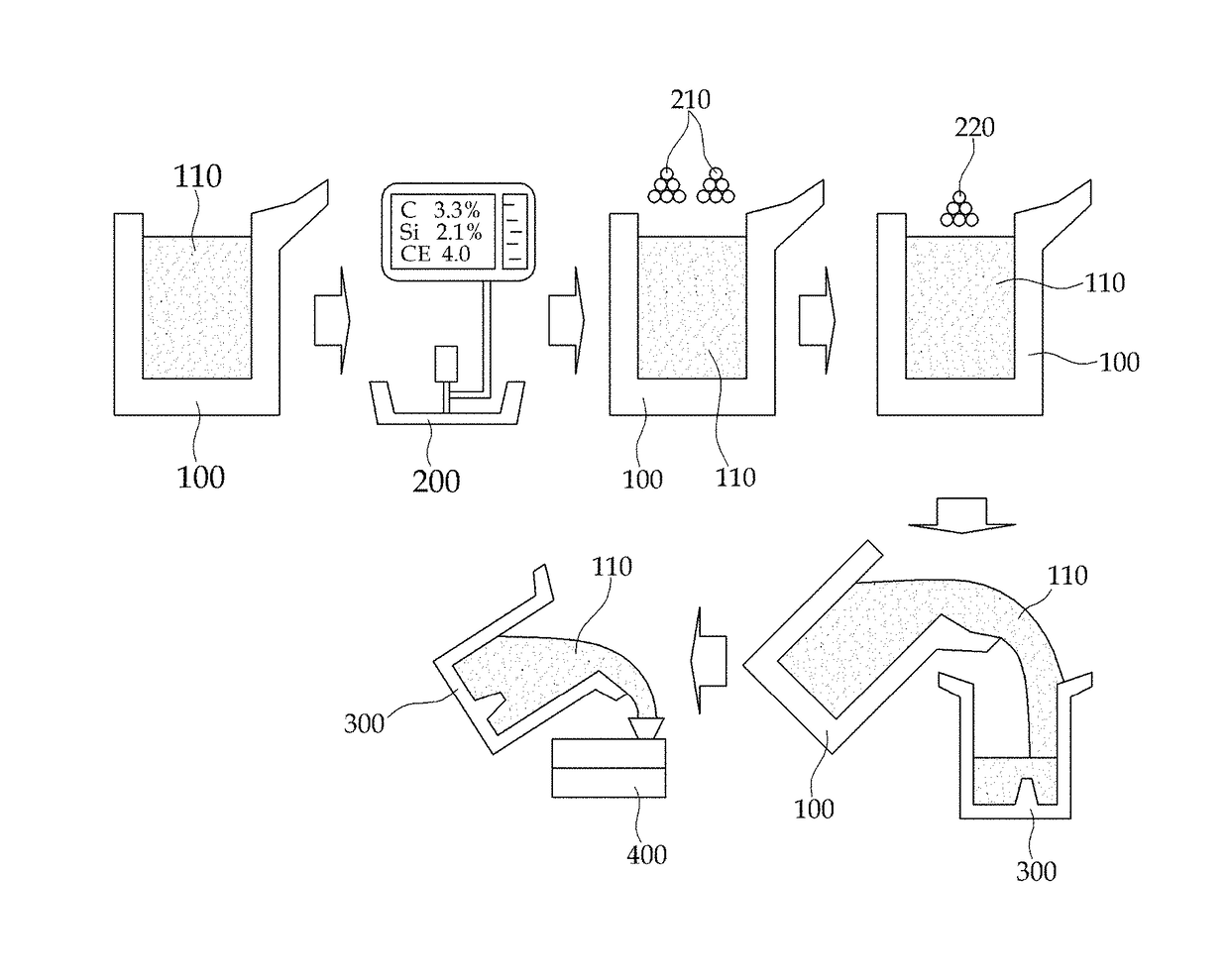
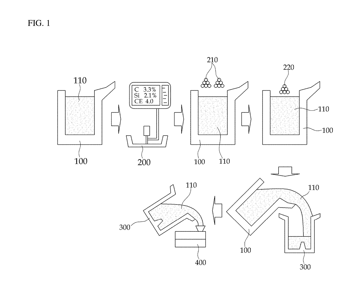
  • Method for manufacturing high strength flake graphite cast iron for an engine body and flake graphite cast iron for an engine body
  • Method for manufacturing high strength flake graphite cast iron for an engine body and flake graphite cast iron for an engine body
  • Method for manufacturing high strength flake graphite cast iron for an engine body and flake graphite cast iron for an engine body

Examples


Embodiment Construction

[0045]Hereinafter, the present disclosure will be described in detail in connection with concrete examples.

[0046]In the present disclosure, a very small amount of strontium (Sr) is used as a component of cast iron. When a content ratio (S / Sr) between sulfur (S) and strontium (Sr) in the cast iron is controlled to be in a predetermined range, the strontium (Sr) reacts with the sulfur (S), and sulfide is formed. The formed sulfide serves as a nucleation site of flake graphite to suppress an occurrence of a chill and to assist growth and cystallization of useful A type flake graphite, so that it is possible to achieve high-strength and excellent processibility and fluidity.

[0047]At this time, the content of the added strontium (Sr) and the content ratio (S / Sr) between the strontium (Sr) and the sulfur (S) in the cast iron are the most important factors in manufacturing high-strength flake graphite cat iron having a tensile strength of 300 MPa or more. Accordingly, it is necessary to li...


PUM

PropertyMeasurementUnit
chill depthaaaaaaaaaa
tensile strengthaaaaaaaaaa
lengthaaaaaaaaaa

Abstract

The present disclosure relates to a flake graphite cast iron simultaneously having high strength, good machinability, and fluidity, to a method for manufacturing same, and to an engine body comprising the flake graphite cast iron for an internal combustion engine and, more particularly, to a method for manufacturing a flake graphite cast iron, for an engine cylinder block and head having improved castability, a low possibility of the occurrence of chill due to ferroalloy, stable tensile strength and yield strength, and good machinability by adding a trace of strontium in a cast iron including carbon (C), silicon (Si), manganese (Mn), sulfur (S), and phosphorus (P), which are five elements of the cast iron, molybdenum (Mo), a high strengthening additive, and copper (Cu) while controlling the ratio (S / Sr) of the sulfur (S) content to the strontium (Sr) content in the cast ion.

Description

CROSS-REFERENCE TO RELATED APPLICATION[0001]This Application is a Section 371 National Stage Application of International Application No. PCT / KR2012 / 010626, filed Dec. 7, 2012 and published, not in English, as WO 2013 / 094904 on Jun. 27, 2013.FIELD OF THE DISCLOSURE[0002]The present disclosure relates to a method for manufacturing high-strength flake graphite cast iron, flake graphite cast iron manufactured by the method, and an engine body comprising the cast iron, and more particularly, to flake graphite cast iron capable of uniformalizing graphite shapes of a thin walled part and a thick walled part, reducing low possibility of the formation of chill and exhibiting high strength and excellent processibility by controlling a very small amount of sulfur (S) and a content of strontium (Sr) to be a predetermined ratio even though ferroalloy is added to achieve high strength, and a method for manufacturing the same.BACKGROUND OF THE DISCLOSURE[0003]In recent years, as environmental reg...

Claims


Application Information

Patent Timeline
Patent Type & Authority Patents(United States)
IPC IPC(8): C22C33/04C22C33/08C22C37/10C21C1/08B22D1/00C22C37/04B22D25/02C22C37/00F02F7/00
CPCC22C33/08B22D1/00B22D25/02C21C1/08C22C33/04C22C37/00C22C37/04C22C37/10C21C2250/00F02F7/0021F02F7/0024
Inventor JUNG, KI HWANSHIM, DONG SEOBYANG, SIKHWANG, JAE HYOUNG
Owner DOOSAN INFRACORE CO LTD
Learn More