
Catalyst component of a motor vehicle exhaust gas cleaning system and use of a catalyst component

a technology of catalyst components and exhaust gas cleaning systems, which is applied in the direction of physical/chemical process catalysts, metal/metal-oxide/metal-hydroxide catalysts, and separation processes, etc., can solve the problem of high oxidation catalyst activity and achieve the effect of long usage period and high cost saving

Active Publication Date: 2017-08-22
DAIMLER TRUCK AG
View PDF28 Cites 2 Cited by
  • Summary
  • Abstract
  • Description
  • Claims
  • Application Information

AI Technical Summary

Benefits of technology

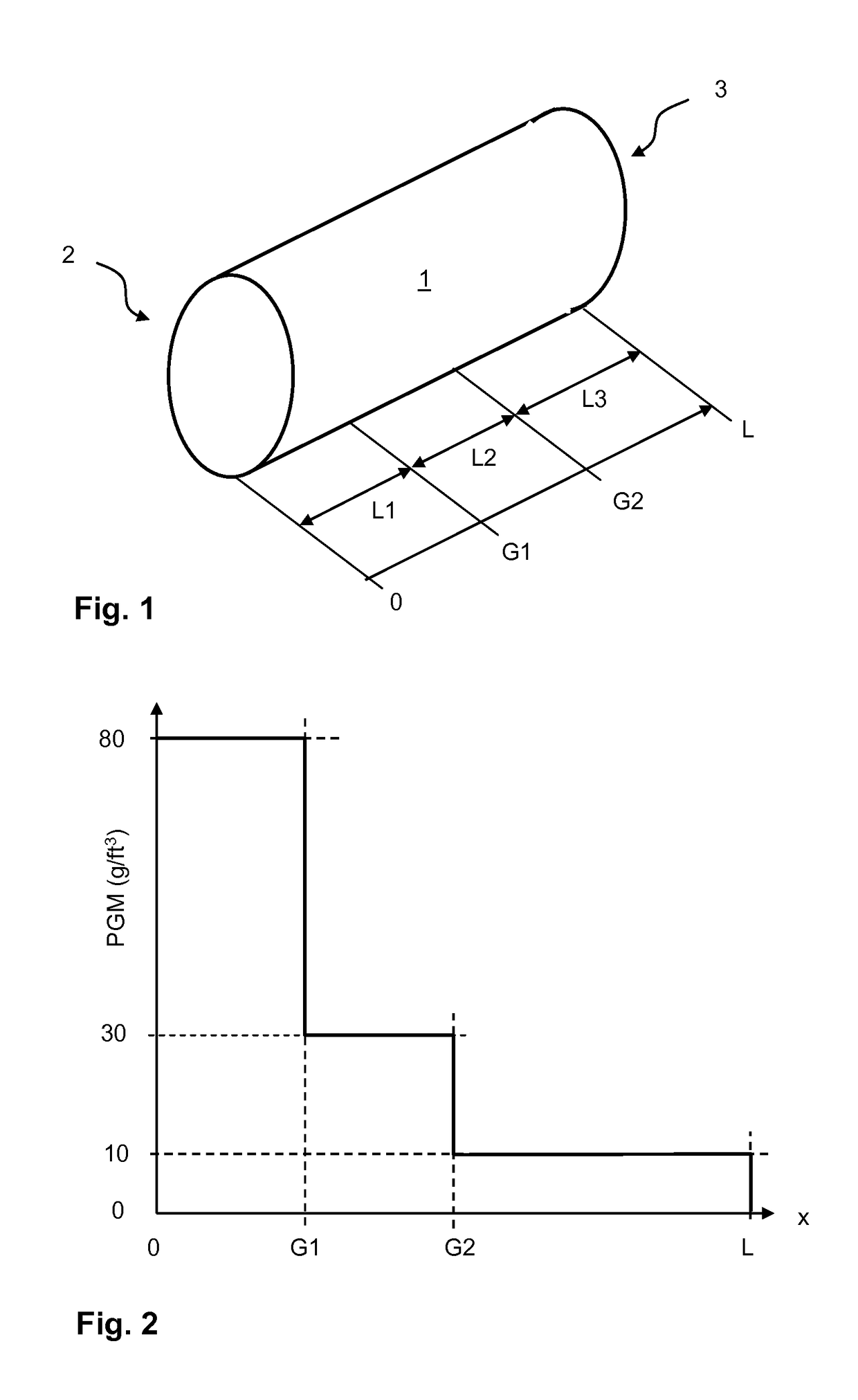
The invention is a catalytic converter component for use in emission control systems of vehicles. The component has a unique design with decreasing precious metal content, which results in a low overall precious metal content and reduced tendency toward oxidation of nitric oxides and sulfur dioxides. The design also has a high level of light-off characteristic, especially for oxidation of hydrocarbons. The coating is a coating with oxidation catalyst activity, and it is preferably formed predominantly from aluminum oxide and zirconium oxide. The precious metals, particularly platinum and palladium, are finely dispersed or contained in a wash coat that has low gas permeability. The precious metal content is determined by the elements platinum and palladium, with an average precious metal content of 15 g / ft3 to 50 g / ft3. The mass ratio of platinum to palladium is preferably 1:2 to 2:1. The precious metal content in different coating zones is also discussed. The use of this catalytic converter component in an emission control system allows for reliable heating of exhaust gas, even at low exhaust gas temperatures, and is particularly suitable for use in utility vehicles.

Problems solved by technology

This results in a high oxidation catalyst activity, in particular with regard to hydrocarbons.

Method used


Image

  • Catalyst component of a motor vehicle exhaust gas cleaning system and use of a catalyst component
  • Catalyst component of a motor vehicle exhaust gas cleaning system and use of a catalyst component
  • Catalyst component of a motor vehicle exhaust gas cleaning system and use of a catalyst component

Examples


Embodiment Construction

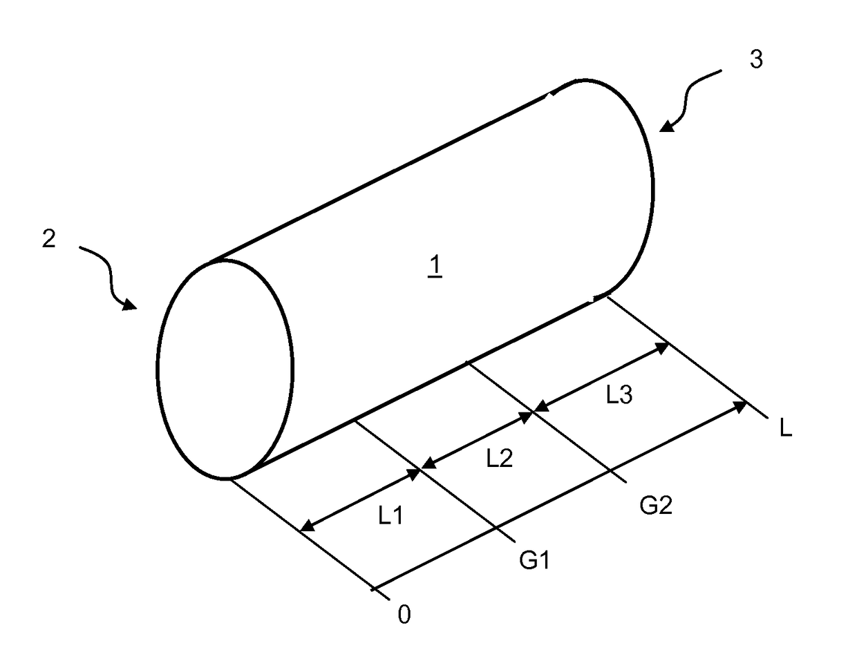
[0021]FIG. 1 schematically illustrates a catalytic converter component 1 according to the invention, as provided for use in an emission control system of a motor vehicle internal combustion engine, not illustrated. In the present case, the catalytic converter component 1 is designed as a honeycomb having an inlet-side end 2 and an outlet-side end 3 with respect to an exhaust gas inlet, and has a longitudinal extent of the length L, viewed in the exhaust gas flow direction. In the present case, the cross-section of the honeycomb is oval; however, a circular cross-section may also be provided. The honeycomb has continuous open channels, the walls of which include a coating having oxidation catalyst activity. The coating preferably contains only platinum and palladium with regard to precious metals of the platinum group, but in any case is free of rhodium. Preferably no other precious metals besides platinum and palladium are provided.

[0022]The catalytic converter component 1 according...


PUM

PropertyMeasurementUnit
temperatureaaaaaaaaaa
temperaturesaaaaaaaaaa

Abstract

A motor vehicle emission control system includes a three zone catalytic converter component having a honeycomb support body with catalytically active coating having a precious metal content applied on the channel walls. The first coating zone extends in the longitudinal direction from the inlet-side end to a first coating boundary and has a first precious metal content. The second coating zone extends in the longitudinal direction from the first coating boundary to a second coating boundary situated downstream from the first coating boundary and has a second precious metal content that is lower than the first precious metal content. The third coating zone extends from the second coating boundary to the outlet-side end and has a third precious metal content that is lower than the second precious metal content. The coating has oxidation catalyst activity and is free of rhodium.

Description

BACKGROUND AND SUMMARY OF THE INVENTION[0001]Exemplary embodiments of the invention relate to a catalytic converter component of a motor vehicle emission control system, and the use of such a catalytic converter component in an emission control system of a motor vehicle for heating exhaust gas.[0002]PCT publication WO 01 / 74476 A1 discloses a catalytic converter component designed as a nitrogen oxides trap, which may have three coating zones, situated one downstream from the other, in the exhaust gas flow direction, having a decreasing content of metals of the platinum group. A high nitrogen oxides conversion capability over a wide temperature range is thus achieved.[0003]Exemplary embodiments of the present invention are directed to providing a cost-effective catalytic converter component for a motor vehicle emission control system having a low overall precious metal content but still having high oxidation catalyst activity, in particular at comparatively low temperatures. Further, ...

Claims


Application Information

Patent Timeline
Patent Type & Authority Patents(United States)
IPC IPC(8): B01J23/40B01J37/02F01N3/035F01N3/20B01D53/94B01J29/072F01N13/00F01N3/10B01J35/04B01J23/42B01J23/44B01J23/56B01J35/00B01J21/06B01J21/04
CPCB01D53/94B01D53/945B01D53/9472B01J23/40B01J29/072B01J35/0006B01J35/04B01J37/0246F01N3/035F01N3/106F01N3/2066F01N13/009F01N13/0093F01N13/0097B01D2255/102B01D2255/9035B01J21/04B01J21/066F01N2510/0682Y02T10/22Y02T10/24Y02A50/20Y02T10/12B01J35/19B01J35/56
Inventor MASSNER, ALEXANDERSINGH, INDERPALZIMMERMANN, FRANK
Owner DAIMLER TRUCK AG
Learn More