Integrated micro/nanogenerator and method of fabricating the same

a micro-nanogenerator and integrated technology, applied in the direction of friction generators, electric devices, generators/motors, etc., can solve the problems of increasing the roughness of the friction surface, increasing the output voltage/current, etc., to improve the improve the output voltage frequency, and improve the effect of friction efficiency and effective friction area

Active Publication Date: 2017-09-12
PEKING UNIV
View PDF5 Cites 4 Cited by
  • Summary
  • Abstract
  • Description
  • Claims
  • Application Information

AI Technical Summary

Benefits of technology

[0007]An object of the present disclosure is to provide an integrated micro / nanogenerator and a method of fabricating the same, wherein three layers of flexible films form a miniaturized generator, and thus essentially form a sandwich-shaped morphology with a gradient difference among charge-binding abilities, which enhances the accumulation of induced charges and thereby increases the output performance of triboelectric generator. Furthermore, the high-dense micro / nano hierarchical structures is fabricated on the surface of flexible film by using the replication process, which significantly increases the roughness of friction surface, thereby further increasing the output voltage / current. Compared with conventional two-layers generator, the intermediate layer of this three-layer sandwich-shaped generator makes electrification with both of upper and lower films during each cycle period, thereby improving the electrification efficiency and achieving frequency multiplication of output signals. In summary, with the integrated micro / nanogenerator and method of fabricating the same according to the present disclosure, there are advantages such as simple process, low cost, high yield, mass production, and great increase the output due to its novel configuration.
[0025]2.4) processing the surface through a DRIE post-treatment process so as to reduce surface energy.
[0030]Compared with prior arts, the present disclosure has the following advantages:
[0031]1. Compared with existing technologies of pure triboelectrification between two-layers of materials, the integrated micro / nanogenerator according to the present disclosure proposes an inventive triboelectrification mechanism among three-layers of flexible films, in which the gradient difference among charge-binding abilities of the three materials is utilized so that materials of the intermediate metal layer make two times of friction with the PDMS layer during each working period, thereby improving the output voltage frequency.
[0032]2. The integrated micro / nanogenerator according to the present disclosure makes use of a three-layer film structure in which the intermediate layer can make friction with both of upper and lower layers of films, thereby greatly improving friction efficiency and effective friction area to greatly increase its output, compared with existing two-layer of films and single-face triboelectrification technologies.
[0033]3. With the method of fabricating the integrated micro / nanogenerator according to the present disclosure, a developed mask-free optimized deep reactive ion etching process is utilized in combination with the casting film transfer process to produce micro-nano hierarchical PDMS films in large-quantities and in large area, thereby greatly increasing film roughness, improving friction efficiency, increasing output voltage / current, and achieving simple processes, low cost and easy industrialization.

Problems solved by technology

Furthermore, the high-dense micro / nano hierarchical structures is fabricated on the surface of flexible film by using the replication process, which significantly increases the roughness of friction surface, thereby further increasing the output voltage / current.

Method used


Image

  • Integrated micro/nanogenerator and method of fabricating the same
  • Integrated micro/nanogenerator and method of fabricating the same
  • Integrated micro/nanogenerator and method of fabricating the same

Examples


Embodiment Construction

[0040]The present disclosure will be described hereinafter in conjunction with embodiments. The present disclosure is not limited to these embodiments, and the scope of the present disclosure is defined in the claims.

[0041]An integrated micro / nanogenerator and specific steps of a method of fabricating the same are described below with reference to FIGS. 1-4.

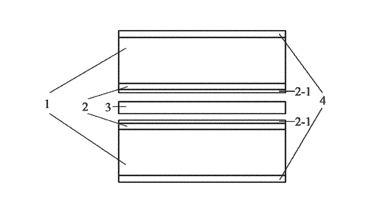
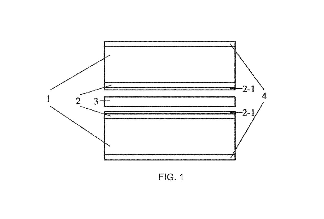
[0042]Referring to FIG. 1, shown is a structural schematic diagram of a integrated micro / nanogenerator of the present disclosure, the integrated micro / nanogenerator has a structure comprising a PET layer 1, a PDMS layer 2, a micro-nano hierarchical PDMS array 2-1, a metal film layer 3 and a conducting layer 4.

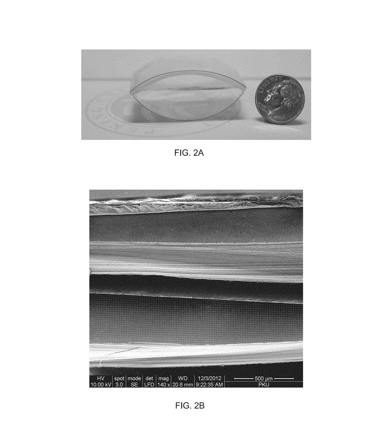
[0043]Referring to FIG. 2, shown are physical drawing and SEM photograph of the integrated micro / nanogenerator of the present disclosure; FIG. 3A is SEM photograph of the micro-nano hierarchical PDMS array of the present disclosure, showing a pyramid array, FIG. 3B is SEM photograph of the micro-nano hierarchical PDMS array ...


PUM

PropertyMeasurementUnit
thicknessaaaaaaaaaa
thicknessaaaaaaaaaa
thicknessaaaaaaaaaa

Abstract

The present disclosure discloses an integrated micro / nanogenerator and a method of fabricating the same The integrated micro / nanogenerator has a structure comprising a conducting layer, a PET layer, a PDMS layer, a micro-nano hierarchical PDMS array and a metal film layer, the conducting layer being manufactured on a surface of the PET layer, the PET layer being made of polyethylene terephthalate; the PDMS layer being made of polydimethylsiloxane, and the micro-nano hierarchical PDMS array being manufactured on a surface of the PDMS layer. The method comprises steps of: 1) fabricating a micro-scale structure on a substrate through a combination of lithography and chemical etching or physical etching; 2) fabricating a nano-scale structure with high density and high depth-to-width ratio directly on a surface of the micro-scale structure through a mask-free optimized deep reactive ion etching process; 3) using a PDMS casting film transfer process by adjusting and controlling process parameters, by means of using the mold of mirco-nano hierarchical array structure as a template; 4) fabricating a conducting layer on a surface of the PET layer by using an evaporation or sputtering or chemical vapor deposition process; 5) bonding the PDMS layer and the PET layer through high temperature bonding or normal temperature physical pressing; and 6) assembling in sequence and packaging the bonded structure obtained in step 5), the metal film layer, and another bonded structure obtained in step 5).

Description

BACKGROUND[0001]Technical Field[0002]The present disclosure generally relates to the field of micro / nano integration technology, and particularly, to an Integrated Micro / nanogenerator and a method of fabricating the same.[0003]Description of the Related Art[0004]Micro-electro-mechanical system (MEMS) is, since being developed in the 1980s, a new-emerging and high technology involved in many realms and leading the development of microelectronics industry in the new century, and thus has attracted so many attentions in the worldwide. A plurality of branches such as optical micro-electro-mechanical system (Optical MEMS), radio-frequency micro-electro-mechanical system (RF MEMS), biomedical micro-electro-mechanical system (Bio-Medical MEMS) and traditional micro-electro-mechanical system (Physical MEMS) and the like have been booming and growing, and it is predicted that the MEMS industry will rapidly grows at a rate of 9.7% from 2011 to 2016 and will reach up to a global gross product ...

Claims


Application Information

Patent Timeline
Patent Type & Authority Patents(United States)
IPC IPC(8): H02N11/00H02N1/04
CPCH02N11/002H02N1/04Y10T29/49119
Inventor ZHANG, HAIXIAZHANG, XIAOSHENGHAN, MENGDIZHU, FUYUN
Owner PEKING UNIV
Why Eureka
Try Eureka