Cardiac tissue cinching

a technology of cardiac tissue and cinching, which is applied in the field of valve repair, can solve the problems of reducing cardiac output, ultimate weakening of the left ventricle, and increasing the total stroke volume, so as to prevent damage to the atrial septum, maintain distance and tension, and reduce regurgitation

Active Publication Date: 2017-10-31
4TECH INC OXO CAPITAL
View PDF696 Cites 69 Cited by
  • Summary
  • Abstract
  • Description
  • Claims
  • Application Information

AI Technical Summary

Benefits of technology

[0009]The torque-delivery tool comprises (a) a torque-delivery cable, which comprises a distal torque-delivery head (b) a distal coupling element that is fixed to a distal end of the distal torque-delivery head, and (c) a distal spring depressor. The tissue anchor comprises (a) a tissue-coupling element, and (b) a proximal anchor head, which is attached to a proximal portion of the tissue-coupling element. The anchor head comprises an axially-stationary shaft and a tether-locking mechanism. The axially-stationary shaft has (a) a distal portion that is axially fixed with respect to the proximal portion of the tissue-coupling element, and (I)) a proximal end that comprises a proximal coupling element. The distal and proximal coupling elements are shaped so as to define corresponding interlocking surfaces, which facilitate coupling of the distal torque-delivery head to the axially-stationary shaft.
[0329]For some applications, the tissue anchor further includes a spring, which is configured to inhibit sliding of the tether through the opening.

Problems solved by technology

Mitral regurgitation of blood from the left ventricle into the left atrium results in increased total stroke volume and decreased cardiac output, and ultimate weakening of the left ventricle secondary to a volume overload and a pressure overload of the left atrium.

Method used


Image

  • Cardiac tissue cinching
  • Cardiac tissue cinching
  • Cardiac tissue cinching

Examples


Embodiment Construction

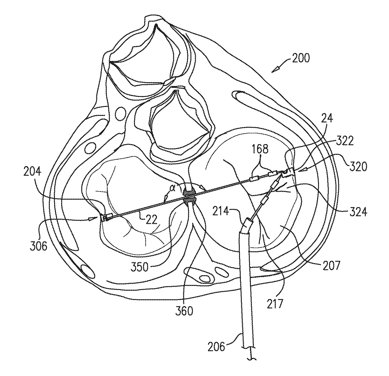
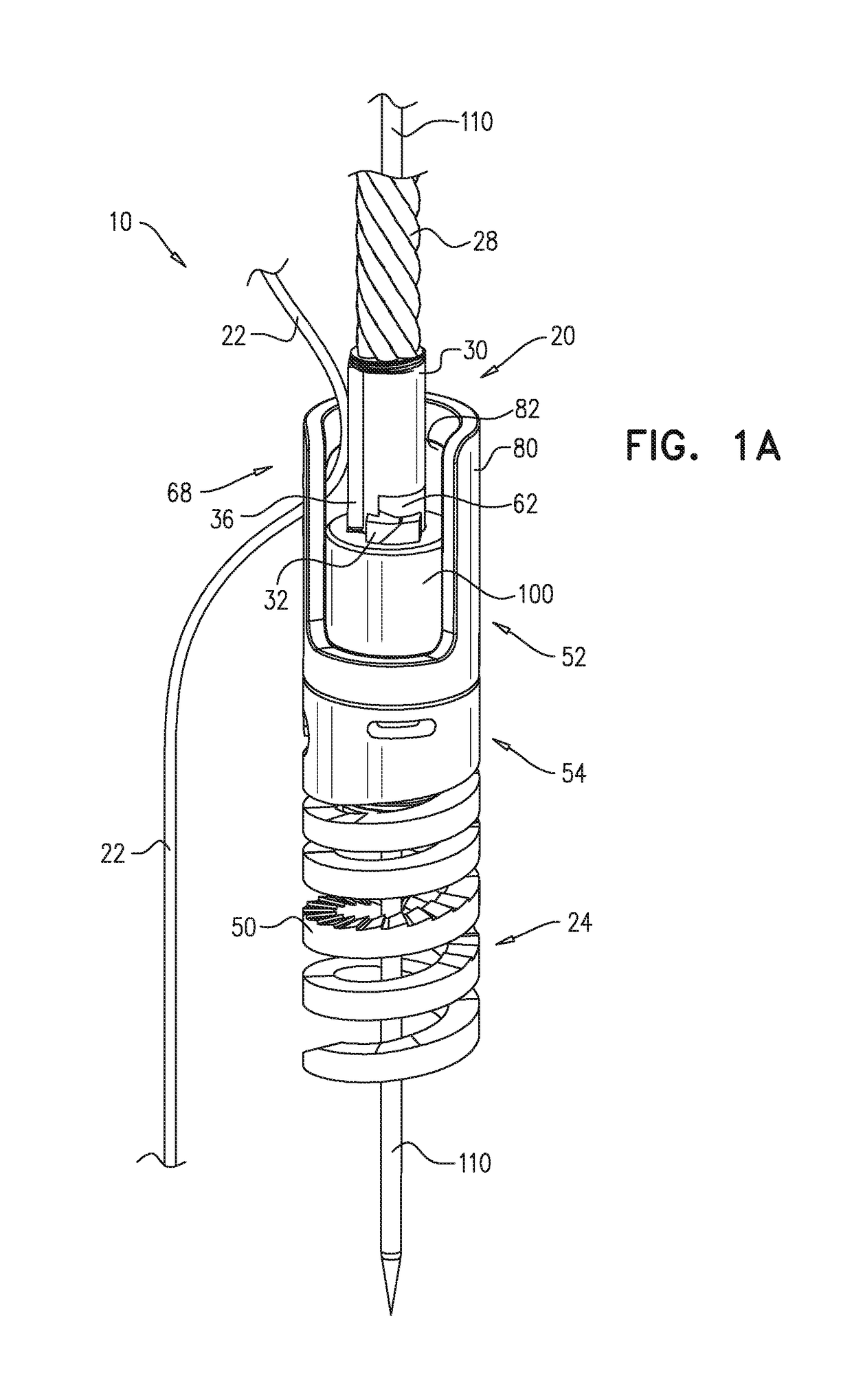
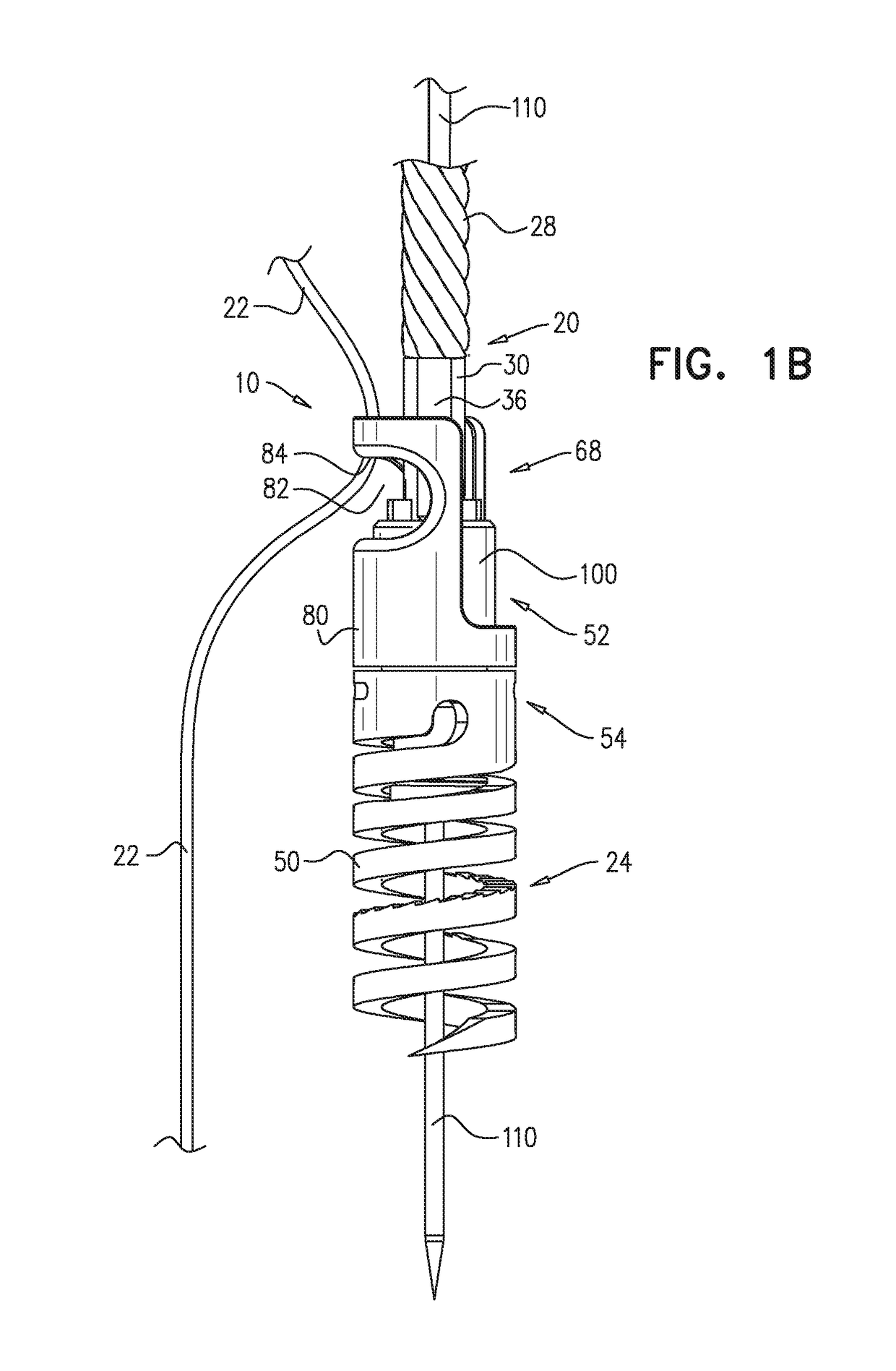
[0389]FIGS. 1A-F are schematic illustrations of a tissue-anchor system 10 in an unlocked state, in accordance with an application of the present invention. FIGS. 2A-B are schematic illustrations of tissue-anchor system 10 in a locked state, in accordance with an application of the present invention. Tissue-anchor system 10 comprises a torque-delivery tool 20, a tether 22, and a tissue anchor 24. Torque-delivery tool 20 is configured to implant tissue anchor 24 in cardiac tissue, and to thereafter lock tether 22 to tissue anchor 24, such that sliding of tether 22 with respect to tissue anchor 24 is inhibited. Typically, tether 22 is tensioned after tissue anchor 24 has been implanted in the cardiac tissue, and after the tether has been tensioned, tether 22 is locked to tissue anchor 24.

[0390]Torque-delivery tool 20 comprises (a) a torque-delivery cable 28, which comprises a distal torque-delivery head 30, (h) a distal coupling element 32 that is fixed to a distal end 34 of distal tor...


PUM


Abstract

A method is provided including making an opening (300) through an atrial septum (302) at a septal site (304) at least 5 mm from a fossa ovalis (330). A first tissue anchor (204) is endovascularly advanced to a left-atrial site (306) on an annulus of a mitral valve (310) or a wall of a left atrium (308) above the annulus. The first tissue anchor (204) is implanted at the left-atrial site (306). A second tissue anchor (24) is endovascularly advanced to a right-atrial site (320) on an annulus of a tricuspid valve (207) or a wall of a right atrium (200) above the annulus. The second tissue (24) anchor is implanted at the right-atrial site (320). The left-atrial site (306) and the right-atrial site (320) are approximated by tensioning a tether (22) that passes through the opening (300) of the atrial septum (302) and connects the first and the second tissue anchors (204, 24). Other embodiments are also described.

Description

CROSS-REFERENCE TO RELATED APPLICATIONS[0001]The present application is the US national stage of International Application PCT / IB2015 / 001196, filed Jun. 14, 2015, which claims priority from (a) U.S. Provisional Application 62 / 014,397, filed Jun. 19, 2014, and (b) U.S. Provisional Application 62 / 131,636, filed Mar. 11, 2015, both of which are assigned to the assignee of the present application and are incorporated herein by reference.FIELD OF THE APPLICATION[0002]Some applications of the present invention relate in general to valve repair. More specifically, some applications of the present invention relate to repair of an atrioventricular valve of a patient.BACKGROUND OF THE APPLICATION[0003]Functional tricuspid regurgitation (FTR) is governed by several pathophysiologic abnormalities such as tricuspid valve annular dilatation, annular shape abnormality, pulmonary hypertension, left or right ventricle dysfunction, right ventricle geometry, and leaflet tethering. Treatment options fo...

Claims


Application Information

Patent Timeline
Patent Type & Authority Patents(United States)
IPC IPC(8): A61F2/24A61B17/00A61B17/04
CPCA61F2/2487A61B17/00234A61B17/0401A61F2/2427A61B17/0466A61B2017/0454A61B2017/00243A61B2017/0414A61B2017/0409A61B2017/0441A61B2017/0448A61B2017/0464
Inventor GILMORE, MICHAELDENTI, PAOLOGUIDOTTI, ANDREALATIB, MOHAMED AZEEMLYNN, KEVINMULLINS, JOHNMAISANO, FRANCESCOZARBATANY, DAVID
Owner 4TECH INC OXO CAPITAL
Why Eureka
Try Eureka