Method of manufacturing secondary battery

a secondary battery and battery technology, applied in the direction of batteries, sustainable manufacturing/processing, cell components, etc., can solve the problems of internal short circuit and the like, significant time and a difficult process, and the battery capacity and performance are dramatically reduced

Active Publication Date: 2017-11-14
LG ENERGY SOLUTION LTD
View PDF29 Cites 1 Cited by
  • Summary
  • Abstract
  • Description
  • Claims
  • Application Information

AI Technical Summary

Benefits of technology

[0019]That is, the method of manufacturing the secondary battery according to the present invention includes applying a predetermined vibration to an electrolytic solution with which an electrode assembly is impregnated. Accordingly, mobility of electrolytic solutions may be increased and thereby interfacial contact properties, namely, wetting properties, of an electrode assembly and an electrolytic solution may be improved.
[0022]That is, ultrasonic waves may give external shock to particles due to intrinsic high frequency and electrolytic solutions shake at the molecular level by the external shock, and thereby mobility of electrolytic solutions may be maximized, and, accordingly, interfacial contact properties (wetting properties) of an electrode may be improved.
[0024]The frequency and the amplitude are optimal values to improve interfacial contact properties between an electrode assembly and an electrolytic solution by maximizing mobility of electrolytic solutions. Therefore, when frequency and amplitude are lower than the values described above, desired effects may not be obtained. On the other hand, when frequency and amplitude are higher than the values described above, efficiency of a manufacturing process is reduced.
[0033]A viscosity of the electrolytic solution to which the vibration is applied may be 0.1 cP or more and 5 cP or less, particularly 2 cP or more and 4 cP or less. Generally, in case of an electrolytic solution having high viscosity, interfacial contact properties between an electrode assembly and an electrolytic solution are reduced and thereby impregnation properties of an electrode assembly may be reduced. However, the present invention applies predetermined vibration to an electrolytic solution and thereby may exhibit desired effects in the high viscosity electrolytic solution described above.
[0039]The cathode current collector is generally fabricated to a thickness of 3 to 500 μm. The cathode current collector is not particularly limited so long as it does not cause chemical changes in the fabricated battery and has high conductivity. For example, the cathode current collector may be made of stainless steel, aluminum, nickel, titanium, sintered carbon, or aluminum or stainless steel surface-treated with carbon, nickel, titanium, silver, or the like. The cathode current collector may have fine irregularities at a surface thereof to increase adhesion between the cathode active material and the cathode current collector. In addition, the cathode current collector may be used in any of various forms including films, sheets, foils, nets, porous structures, foams, and non-woven fabrics.
[0044]The anode current collector is generally fabricated to a thickness of 3 to 500 μm. The anode current collector is not particularly limited so long as it does not cause chemical changes in the fabricated battery and has conductivity. For example, the anode current collector may be made of copper, stainless steel, aluminum, nickel, titanium, sintered carbon, copper or stainless steel surface-treated with carbon, nickel, titanium, silver, or the like, or aluminum-cadmium alloys. Similar to the cathode current collector, the anode current collector may also have fine irregularities at a surface thereof to increase adhesion between the anode active material and the anode current collector. In addition, the anode current collector may be used in any of various forms including films, sheets, foils, nets, porous structures, foams, and non-woven fabrics.

Problems solved by technology

However, due to material characteristics such as a cathode, an anode and a separator which are hydrophobic, and an electrolytic solution which is hydrophilic, substantial time and a difficult process are required until an electrode and a separator are wetted with an electrolytic solution.
The amount of an electrolytic solution in a battery manufactured according to such a process battery is partially insufficient, and thereby battery capacity and performance are dramatically reduced.
However, when the methods are used, an electrode assembly and an electrolytic solution may be transformed and thereby problems such as internal short circuit and the like may occur.

Method used


Image

  • Method of manufacturing secondary battery
  • Method of manufacturing secondary battery

Examples


example 1

[0059]A porous separator was interposed between a cathode including a cathode active material and an anode including an anode active material to manufacture an electrode assembly. The electrode assembly was embedded in a battery case and then a non-aqueous lithium electrolytic solution including ethylene carbonate and ethylmethyl carbonate mixed in a volumetric ratio of 3:7 was injected thereinto. Subsequently, vibration having a frequency of 40 kHz was applied thereto, resulting in completion of a secondary battery.

experimental example 1

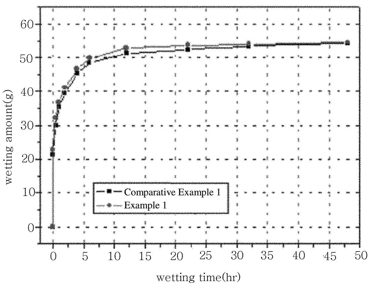
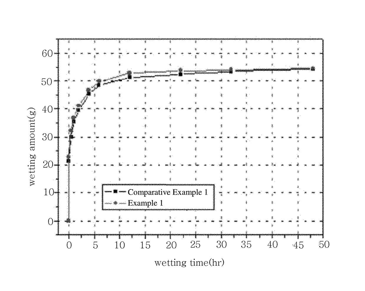
[0061]In each of Example 1 and Comparative Example 1, the amount of an impregnated electrolytic solution according to time was measured after injecting an electrolytic solution. Results are illustrated in FIG. 1 below.

[0062]In accordance with FIG. 1 below, it can be confirmed that the secondary battery, in which vibration was added to an electrolytic solution, manufactured according to Example 1 exhibits improved electrolytic solution impregnation amount and impregnation rate when compared to the secondary battery, in which vibration was not added to an electrolytic solution, manufactured according to Comparative Example 1.


PUM

PropertyMeasurementUnit
frequencyaaaaaaaaaa
viscosityaaaaaaaaaa
viscosityaaaaaaaaaa

Abstract

Disclosed is a method of manufacturing a secondary battery wherein an electrode assembly impregnated with an electrolytic solution is embedded in a battery case,wherein interfacial contact properties (i.e. wetting) of the electrode assembly and the electrolytic solution are improved through a process including:(a) impregnating an electrode assembly having a separator interposed between a cathode and an anode with an electrolytic solution; and(b) applying vibration having a frequency of 20 to 100 kHz to an electrolytic solution with which the electrode assembly is impregnated.A secondary battery manufactured according to the method may have improved ionic conductivity, electronic conductivity and the like and, as such, may have improved electrochemical performance.

Description

CROSS-REFERENCE TO RELATED APPLICATION[0001]This application is a national phase entry under 35 U.S.C. §371 of International Application No. PCT / KR2013 / 010103, filed Nov. 8, 2013, which claims priority to Korean Patent Application No. 10-2012-0125795, filed on Nov. 8, 2012, the disclosures of which are incorporated herein by reference.TECHNICAL FIELD[0002]The present invention relates to a method of manufacturing a secondary battery wherein an electrode assembly impregnated with an electrolytic solution is embedded in a battery case,[0003]wherein interfacial contact properties (i.e. wetting) of the electrode assembly and the electrolytic solution are improved through a process including:[0004](a) impregnating an electrode assembly having a separator interposed between a cathode and an anode with an electrolytic solution; and[0005](b) applying vibration having a frequency of 20 to 100 kHz to an electrolytic solution with which the electrode assembly is impregnated.BACKGROUND ART[0006...

Claims


Application Information

Patent Timeline
Patent Type & Authority Patents(United States)
IPC IPC(8): H01M10/052H01M10/058H01M2/02H01M2/36H01M10/04H01M10/0568H01M10/0569H01M50/609
CPCH01M10/049H01M2/0202H01M2/0237H01M2/36H01M10/052H01M10/058H01M2/02Y10T29/49115H01M2/362H01M10/0568H01M10/0569H01M2220/20H01M2220/30H01M2300/0037Y02T10/7011H01M10/04H01M50/609Y02E60/10Y02P70/50H01M10/44H01M10/0563H01M2300/002H01M2300/0025Y02T10/70
Inventor CHUNG, MIKYUNGKIM, SOOJINCHANG, SUNG-KYUNUHM, IN SUNGCHANG, WON SEOK
Owner LG ENERGY SOLUTION LTD
Why Eureka
Try Eureka