Metal foil, metal foil manufacturing method and method for manufacturing electrode using the same

a metal foil and manufacturing method technology, applied in the manufacturing process of electrodes, cell components, electrochemical generators, etc., can solve the problems of reducing the output properties of the electrode in charge/discharge cycles, increasing the interfacial resistance between the metal foil and the electrode material, and reducing the calendar life of the electrode, so as to improve the coating performance of the conductive resin layer

Active Publication Date: 2017-11-21
KOREA JCC CO LTD
View PDF2 Cites 3 Cited by
  • Summary
  • Abstract
  • Description
  • Claims
  • Application Information

AI Technical Summary

Benefits of technology

[0010]Accordingly, the present invention has been made in order to solve the above-described problems, and it is an object of the present invention to provide a metal foil, a metal foil manufacturing method and a method for manu

Problems solved by technology

The oxide layer or the oil layer has the problem of increasing the interfacial resistance between the aluminum foil and the electrode material.
Particularly, the oil layer has the problem of reducing the adhesion of the electrode material to cause the peeling of the electrode material as charge/discharge cycles are repeated, thereby reducing the output properties of the electrode in charge/discharge cycles and reducing the calendar life of the electrode.
This metal foil has problems in that, because an oxide layer or an oil layer remain on

Method used


Image

  • Metal foil, metal foil manufacturing method and method for manufacturing electrode using the same
  • Metal foil, metal foil manufacturing method and method for manufacturing electrode using the same
  • Metal foil, metal foil manufacturing method and method for manufacturing electrode using the same

Examples


example 1

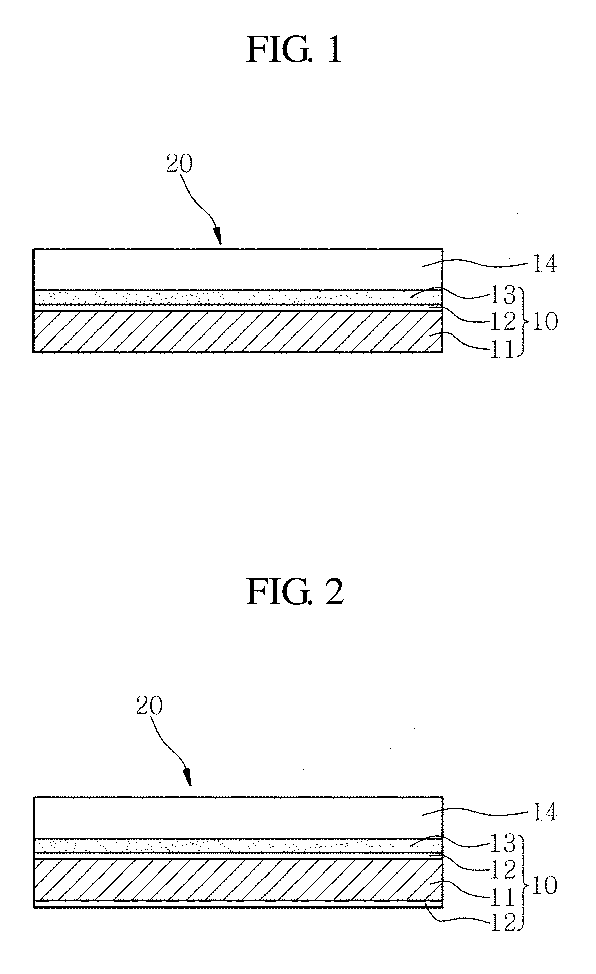
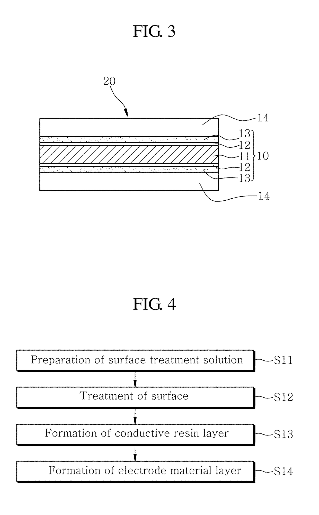
[0067]In Example 1 of the present invention, a physical test was performed to examine the state of application of a conductive resin solution used to form the conductive resin layer 13, based on whether the surface treatment layer 12 (shown in FIG. 1) was formed on the surface of the metal base substrate 11 (shown in FIG. 1) of the metal foil 10 (shown in FIG. 1). In Example 1 of the present invention, an aluminum foil (A1235) was used as the metal base substrate 11.

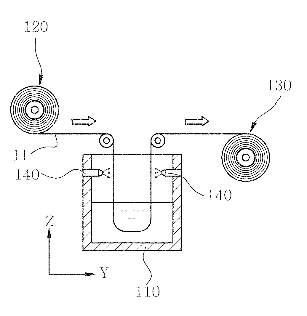
[0068]The aluminum foil (A1235) used had a thickness of 20 μm, and a surface treatment layer 12 was formed on the surface of the aluminum foil. The surface treatment layer 12 was formed to have a surface energy value of 44 dyne / cm by dipping the aluminum foil in a surface treatment solution (stored in a surface processing bath 110 (shown in FIG. 5)) at a temperature of 60° C. for 8 seconds while spraying the surface treatment solution onto the surface of the aluminum foil through a nozzle 140 (see FIG. 5). Herein, the su...

example 2

[0072]In Example 2 of the present invention, a conductive resin layer 13 was prepared in order to perform a physical test (i.e., tape peeling test). Herein, the conductive resin layer 13 was prepared by drying the conductive resin solution (shown in each of FIGS. 6 and 7) in a drying furnace (not shown) at 180° C. for 8 minutes.

[0073]In the tape peeling test, to the surface of the conductive resin layer 13 formed by drying the conductive resin solution shown each of FIGS. 6 and 7, a polypropylene adhesive tape 150 (shown in each of FIGS. 8 and 9) having a width of 10 mm and a length of 150 mm was adhered by applying an uniform load of 20±0.4 N (Newton) with the reciprocating movement of a press roller. After the adhesive tape was adhered to the surface of the conductive resin layer 13, the adhesive tape 150 was peeled off at a speed of 10 mm / s and an angle of 90° by use of an automatic adhesion tester (not shown), and whether the conductive resin layer 13 was peeled off was observed...

example 3

[0077]In Example 3 of the present invention, an electrode 20 (shown in FIG. 1) and a lithium ion secondary battery (not shown) comprising the electrode 20 were manufactured in order to test electrical properties, including capacity retention rate, impedance, and battery life span.

[0078]In Example 3 of the present invention, the electrode 20 was manufactured by applying an electrode material layer 14 (shown in FIG. 1) to the conductive resin layer 13 formed in Example 2 of the present invention, that is, the conductive resin layer 13 formed by drying the conductive resin solution shown in each of FIGS. 6 and 7.

[0079]The electrode material layer 14 was manufactured as a cathode and an anode. For example, a cathode electrode 20 and an anode electrode 20 were manufactured by applying each of a cathode electrode and an anode material on the surface of the conductive resin layer 13 formed by drying the conductive resin solution shown in FIG. 6. In addition, using the conductive resin laye...


PUM

PropertyMeasurementUnit
Temperatureaaaaaaaaaa

Abstract

Provided are a metal foil, a metal foil manufacturing method and a method for manufacturing an electrode using the same, in which the adhesion between the metal foil and a conductive resin layer and the coating performance of the conductive resin layer can be improved by treating the surface of the metal foil. The metal foil comprises: a metal base substrate; a surface treatment layer formed on at least one surface of the metal base substrate by treating the surface of the metal base substrate; and a conductive resin layer applied to the surface of the surface treatment layer, wherein the surface treatment layer has a surface energy of 34-46 dyne/cm.

Description

CROSS-REFERENCE TO RELATED APPLICATION[0001]This application claims the benefit of Korean Patent Application No. 10-2016-0062864, filed on May 23, 2016 in the Korean Intellectual Property Office, the disclosure of which is incorporated herein by reference.BACKGROUND OF THE INVENTION1. Field of the Invention[0002]The present invention relates to a metal foil, a metal foil manufacturing method and a method for manufacturing an electrode using the same, and more particularly, to metal foil, a metal foil manufacturing method and a method for manufacturing an electrode using the same, in which the adhesion between the metal foil and a conductive resin layer and the coating performance of the conductive resin layer can be improved by treating the surface of the metal foil.2. Description of the Related Art[0003]Conventional lithium ion secondary batteries or electric double layer capacitors have electrodes, and each of the electrodes comprises an electrode material and a current collector ...

Claims


Application Information

Patent Timeline
IPC IPC(8): B05D5/12H01M4/525H01M4/66H01M10/0525H01M4/62H01M4/583H01M4/04
CPCH01M4/668H01M10/0525H01M4/525H01M4/623H01M4/583H01M4/0404H01M4/667C23C22/63C23C22/66H01G11/66H01G11/68H01G11/84H01M4/661H01M4/663H01M10/052Y02E60/10B05D7/14B05D7/24B05D2502/00C23C26/00Y02E60/13
Inventor SHIN, DAL WOOLEE, MUN SOOSHIN, JIN SIKHAN, SO YEONKANG, RAE CHEOLPARK, JI YOON
Owner KOREA JCC CO LTD
Why Eureka
Try Eureka