Method of forming a solder bump structure
a technology of solder bumps and solder joints, which is applied in the direction of printed element electric connection formation, semiconductor/solid-state device details, conductors, etc., can solve the problems of high process cost, difficult process management of electroless plating, and relatively high production cos
- Summary
- Abstract
- Description
- Claims
- Application Information
AI Technical Summary
Benefits of technology
Problems solved by technology
Method used
Image
Examples
embodiment 1
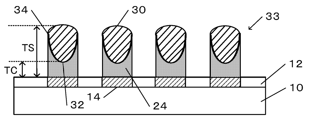
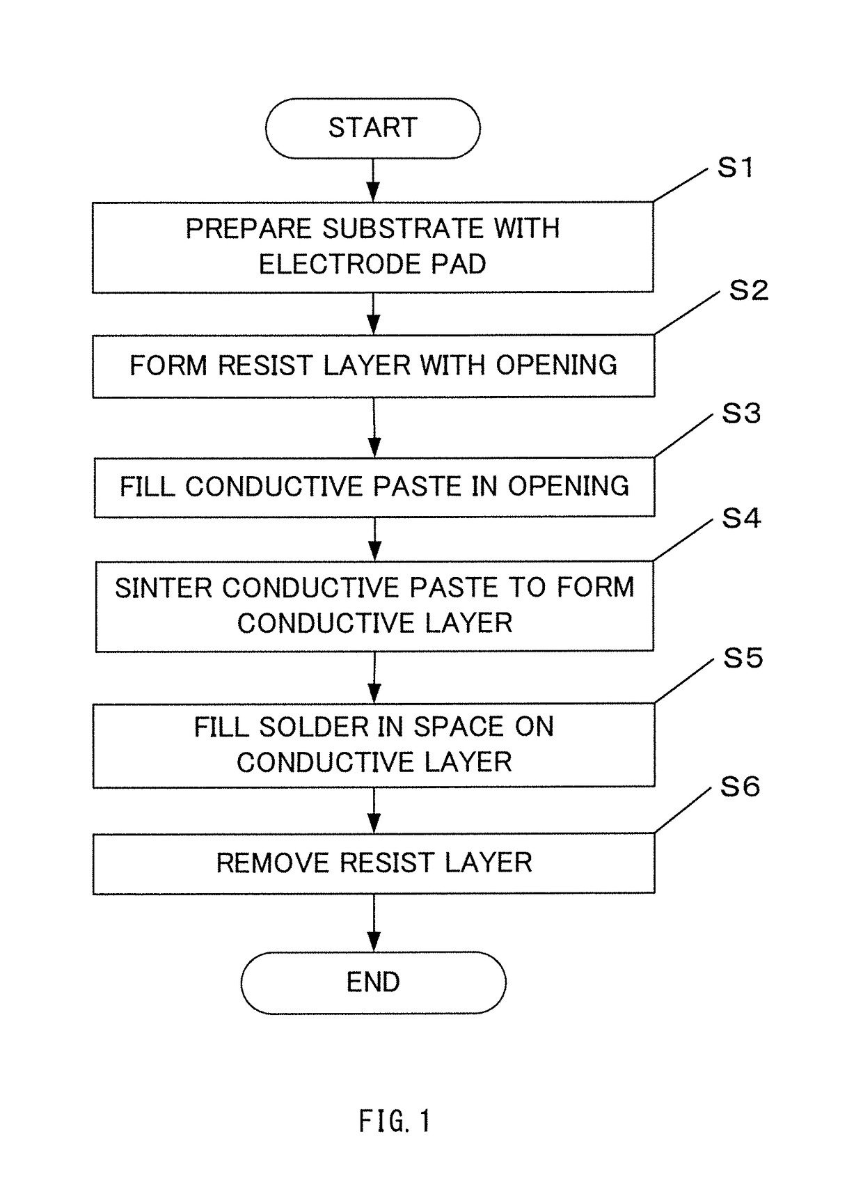
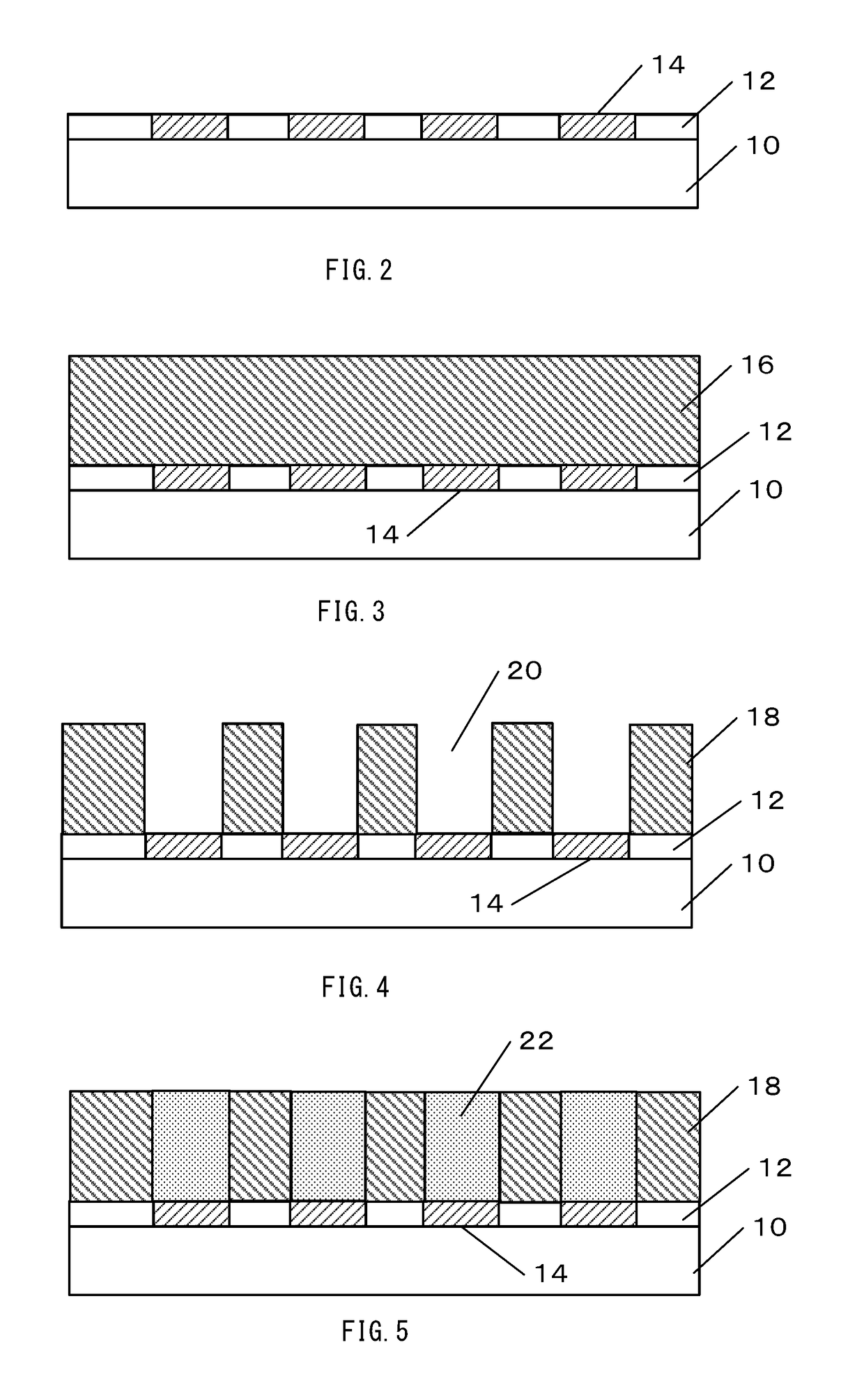
[0021]Referring FIG. 1 and FIG. 2, in step S1, a substrate 10 is prepared first. The substrate 10 has a surface on which electrode pads 14 have been formed between patterned insulating layers 12. The electrode pads 14 can include metal such as Aluminum (Al), for example. The insulating layers 12 can include silicon oxide (SiO2), for example. The substrate 10 can include semiconductor wafer such as a Si wafer, a semiconductor chip / die, or a circuit board. The material of the semiconductor wafer or chip is not limited to specific types. The substrate 10 can include a plurality of wiring layers (including circuits, devices such as a transistor) and insulating layers. The wiring layers can electrically connected to the electrode pads 14. The substrate 10 may include the lamination (stack) of a plurality of semiconductor substrates.
[0022]Referring FIG. 3, in step S2, a resist layer 16 is formed on the substrate 10 as shown in FIG. 3. A resist material is applied on the substrate 10 using...
embodiment 2
[0028]Referring FIG. 9 to FIG. 12, another embodiment of the method of the present invention is explained. Steps S10 to S40 in FIG. 9 are same as steps S1 to S4 in FIG. 1 as described above. Steps 50 to 70 are added as new steps in FIG. 9. FIG. 10 shows a cross-sectional diagram after step S40 which performs sintering of the conductive paste 22 in the opening 20 in FIG. 5. In FIG. 10, a thin conductive layer 34 is formed after the sintering process. The thin conductive layer 34 covers the side wall of the resist layer 18 and the surface of the electrode pad 14 in the opening 20 as shown in FIG. 10. The thickness TC1 of the central portion 35 of the conductive layer 34 is thinner than the predetermined thickness in the range of 1 to 50 micrometers, for example. Therefore, it is necessary to form additional conductive layers on the conductive layer 34 in order to ensure a predetermined thickness.
[0029]In step S50, additional conductive paste 36 is filled in the opening 26 of the resis...
embodiment 3
[0031]Referring FIG. 1, FIG. 5, and FIG. 7, another embodiment of the method of the present invention is explained. In this embodiment, the filling of the conductive paste 22 in step S3 of FIG. 1 and FIG. 5 is performed using IMS process which is used in step S5 of filling of solder 30 instead of screen printing. In step S3, the conductive paste 22 is injected in place of solder under predetermined pressure by IMS process. By using the IMS in Step S3, it is possible to perform steps S3 to Step S5 under one IMS process. That is, even sintering of step S4 can be performed in the IMS process. As a result, it is possible to achieve a further shortening of the production time and simplification of the manufacturing process to form the solder bump structure.
[0032]The embodiment of the present invention has been described with reference to the accompanying drawings. However, the present invention is not limited to the embodiment. The present invention can be carried out in forms to which v...
PUM
| Property | Measurement | Unit |
|---|---|---|
| volume shrinkage | aaaaa | aaaaa |
| thickness | aaaaa | aaaaa |
| conductive | aaaaa | aaaaa |
Abstract
Description
Claims
Application Information
 - R&D
- Intellectual Property
- Life Sciences
- Materials
- Tech Scout
- Unparalleled Data Quality
- Higher Quality Content
- 60% Fewer Hallucinations
Browse by: Latest US Patents, China's latest patents, Technical Efficacy Thesaurus, Application Domain, Technology Topic, Popular Technical Reports.
© 2025 PatSnap. All rights reserved.Legal|Privacy policy|Modern Slavery Act Transparency Statement|Sitemap|About US| Contact US: help@patsnap.com


