Split cycle engine and method of operation

a technology of split cycle engine and split cycle, which is applied in the direction of engines, machines/engines, mechanical equipment, etc., can solve the problems of reducing the compression ratio, requiring compression, and affecting the efficiency of the engine, so as to achieve the effect of progressively reducing the concentration of fuel

Inactive Publication Date: 2018-01-16
ZAJAC JOHN
View PDF16 Cites 1 Cited by
  • Summary
  • Abstract
  • Description
  • Claims
  • Application Information

AI Technical Summary

Benefits of technology

[0011]These and other objects are achieved in accordance with the invention by providing a split cycle engine for burning gaseous fuel which includes a first compression chamber for compressing the gaseous fuel, means for supplying the gaseous fuel to the first compression chamber at a level of concentration that prevents predetonation of the fuel during compression, a second compression chamber for compressing air, a combustion chamber in which the compressed fuel and air are combined to reduce the concentration of the fuel to a level that allows the fuel to burn and expand in the combustion chamber, and an expansion chamber having an output member which is driven by expanding gas from the combustion chamber. Turbochargers or blowers pressurize and increase the mass of the fuel and air delivered to the respective compression chambers, and the concentration of the fuel is progressively reduced by the injection of air at spaced intervals as the fuel travels toward the compression chamber.

Problems solved by technology

Even though natural gas and synthesis gas (syngas) may be available in abundant supply, they are often not used as fuel for Otto cycle and diesel engines because of problems such as predetonation.
However, since the efficiency of the engine is directly related to the compression ratio, reducing the compression ratio can significantly impact the efficiency of an engine.
This complicates the problem and can also require compression to be kept at a lower level.
Consequently, present engines are inefficient and dirty.
Using detuned diesel engines also creates a large amount of particles, soot, smoke, and other pollutants.
Some jurisdictions currently provide air pollution exemptions for such engines because they think that burning the biomass from which the fuels are made would produce even more pollutants.
However, with gaseous fuels such as natural gas and syngas, great volumes of gas have to be injected at high pressures (e.g., in the range of 500 to 5,000 psi), and the work required to inject the large volumes at high pressure is problematical.
However, this can also cause predetonation or knocking which can quickly and permanently damage the engine.

Method used


Image

  • Split cycle engine and method of operation
  • Split cycle engine and method of operation
  • Split cycle engine and method of operation

Examples


Embodiment Construction

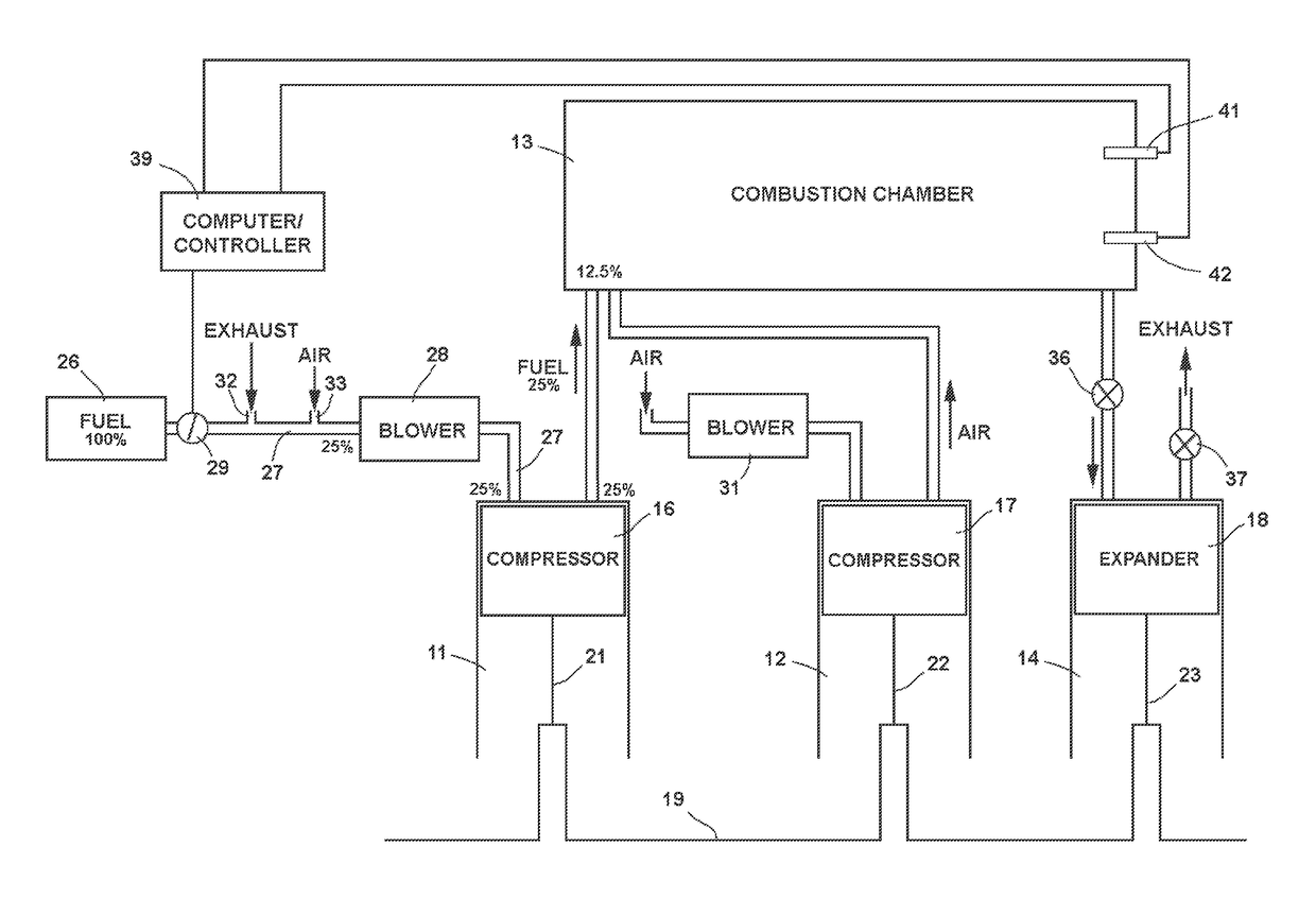
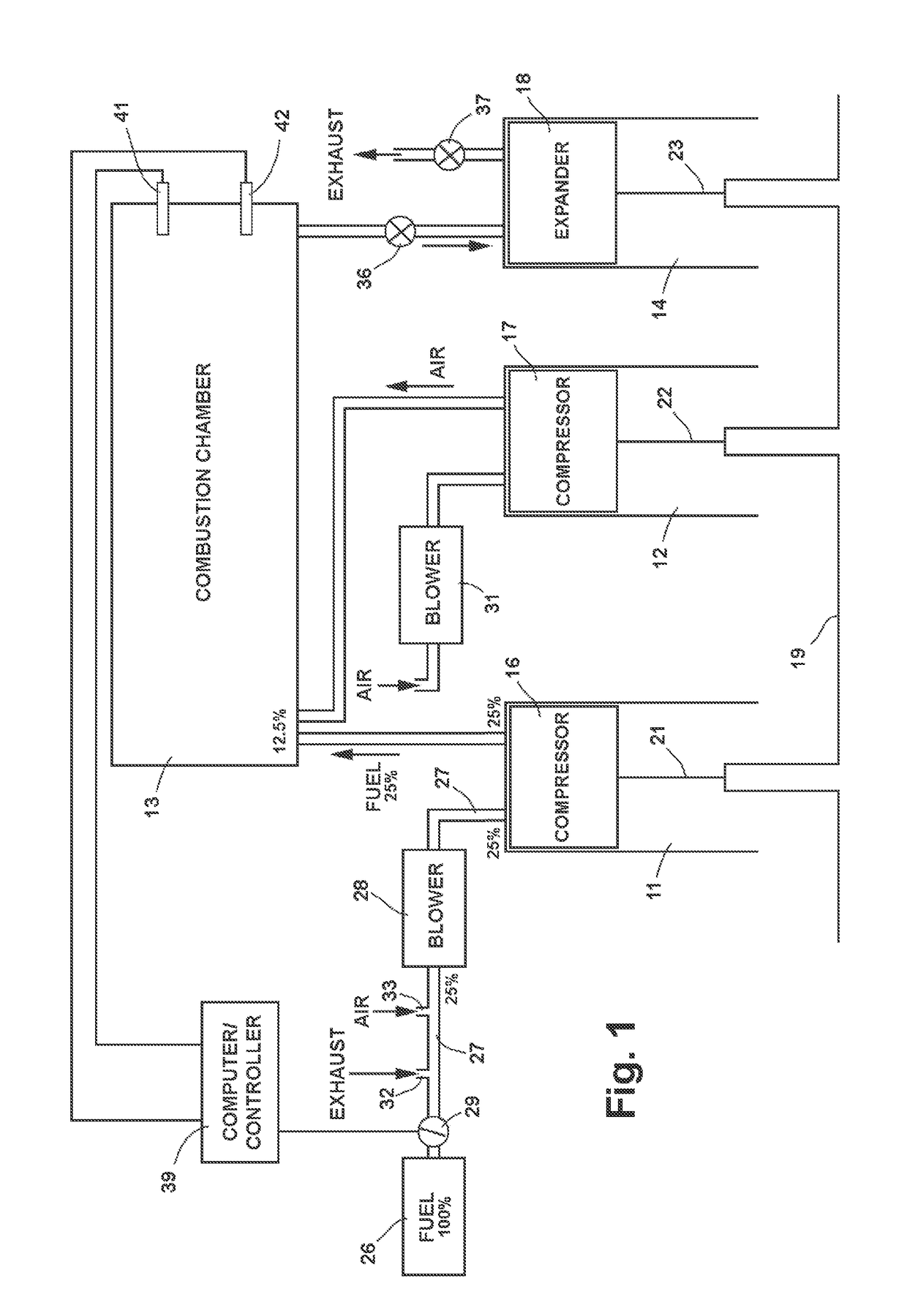
[0015]As illustrated in FIG. 1, the engine has a pair of compression cylinders 11, 12, a combustion chamber 13, and an expansion cylinder 14, with reciprocating pistons 16, 17, 18 in the compression and expansion cylinders forming chambers of variable volume. The pistons are connected to a crankshaft 19 by connecting rods 21, 22, 23 for movement in concert between top dead center (TDC) and bottom dead center (BDC) positions in the cylinders, with each of the pistons making one upstroke and one downstroke during each revolution of the crankshaft. The piston 18 in expansion cylinder 14 is at times referred to hereinafter as an output member.

[0016]Fuel is supplied to the combustion chamber from a tank 26 via a fuel line 27, a turbocharger or blower 28, and compression cylinder 11, with a butterfly valve 29 or other suitable controller in the fuel line for controlling the amount of fuel entering the blower.

[0017]Air is supplied to the combustion chamber from compression cylinder 12, wit...


PUM


Abstract

Split cycle engine that runs on gaseous fuels such as natural gas and synthesis gas (syngas) and to a method of operating the same. The engine includes a first compression chamber for compressing the gaseous fuel, means for supplying the gaseous fuel to the first compression chamber at a level of concentration that prevents predetonation of the fuel during compression, a second compression chamber for compressing air, a combustion chamber in which the compressed fuel and air are combined to reduce the concentration of the fuel to a level that allows the fuel to burn and expand in the combustion chamber, and an expansion chamber having an output member which is driven by expanding gas from the combustion chamber.Turbochargers or blowers pressurize and increase the volume of the fuel and air delivered to the respective compression chambers, and the concentration of the fuel is progressively reduced by the injection of air at spaced intervals as the fuel travels toward the compression chamber.

Description

BACKGROUND OF THE INVENTION[0001]Field of Invention[0002]This invention pertains generally to combustion engines and, more particularly, to a split cycle engine that runs on gaseous fuels such as natural gas and synthesis gas (syngas) and to a method of operating the same.[0003]Related Art[0004]Even though natural gas and synthesis gas (syngas) may be available in abundant supply, they are often not used as fuel for Otto cycle and diesel engines because of problems such as predetonation. In order to avoid knocking and serious damage resulting from predetonation, engines running on these fuels are sometimes detuned and run on lower compression ratios. However, since the efficiency of the engine is directly related to the compression ratio, reducing the compression ratio can significantly impact the efficiency of an engine. For example, reducing the compression ratio from 16:1 to 9:1 in a diesel engine causes a reduction in efficiency on the order of 30%.[0005]Syngas is made by gasifi...

Claims


Application Information

Patent Timeline
Patent Type & Authority Patents(United States)
IPC IPC(8): F02B43/00F02D19/02F02M21/00F02B43/10F02B43/04
CPCF02B43/10F02D19/022F02B43/04Y02T10/32Y02T10/30
Inventor ZAJAC, JOHN
Owner ZAJAC JOHN
Why Eureka
Try Eureka