Crankcase ventilation pressure management for turbocharged engine

a turbocharged engine and crankcase technology, applied in the direction of crankcase ventilation, combustion engines, machines/engines, etc., can solve the problems of difficult or impossible to find a restriction level that provides the needed vacuum, and the seals fail to meet the requirements

Active Publication Date: 2018-03-06
FORD GLOBAL TECH LLC
View PDF18 Cites 4 Cited by
  • Summary
  • Abstract
  • Description
  • Claims
  • Application Information

AI Technical Summary

Benefits of technology

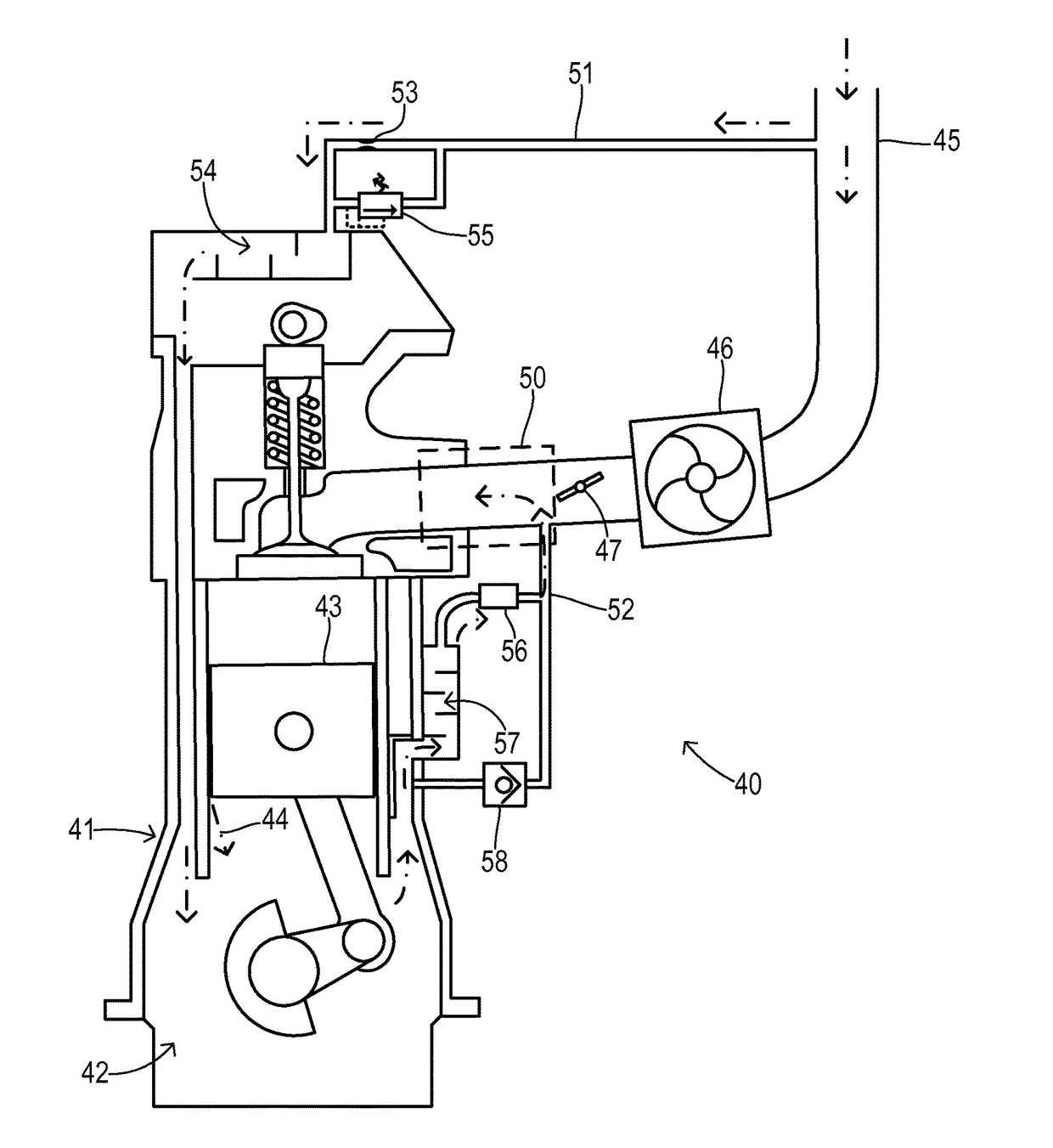
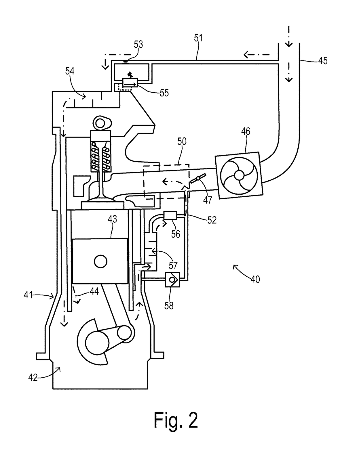
[0010]The present invention employs a PCV bypass which is sized to permit an appropriate flow of pressurized air during a boosted state from the intake manifold into the crankcase for diluting the blowby gases. The flow control components are arranged in a way that enables independent sizing of components and the ability to obtain desirable crankcase pressure under all operating conditions.

Problems solved by technology

In particular, the high pressure introduced downstream of the compressor (e.g., in the intake manifold) could reverse the flow in the vent line thereby pressurizing the crankcase to an extent that could cause failure of the seals.
However, if the crankcase fresh air feed is restricted too much then the crankcase may become positively pressurized under full load conditions (i.e., when the restricted vent line or breather reverses flow to evacuate the blowby gases into the low pressure section of the air inlet system), which can jeopardize the crankcase sealing integrity.
It is often difficult or impossible to find a restriction level that provides the needed vacuum at idle while not creating an undesirably large positive pressure during full load operation.
In such a system, however, undiluted blowby gases are collected to be ingested by the engine.
Oil degradation such as sludging, varnishing, and emulsification can occur due to insufficient fresh air being mixed with the blowby gases in the crankcase prior to reaching the oil separator.
Undiluted blowby gases may accumulate high levels of unburned fuel, such as during a decel fuel cutoff, which may increase pollution or cause other problems.

Method used


Image

  • Crankcase ventilation pressure management for turbocharged engine
  • Crankcase ventilation pressure management for turbocharged engine
  • Crankcase ventilation pressure management for turbocharged engine

Examples


Embodiment Construction

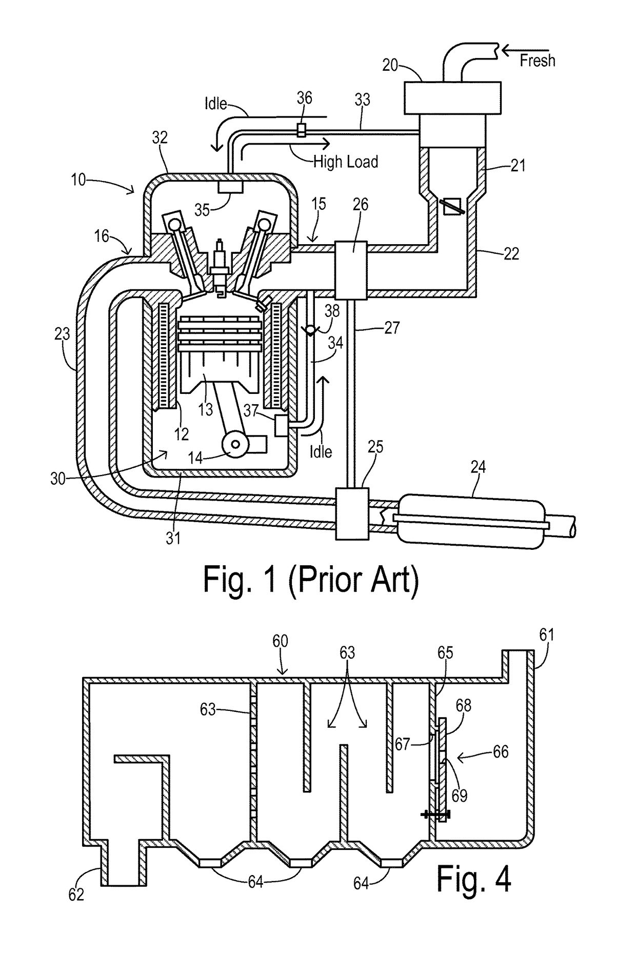
[0017]Referring to FIG. 1, an internal combustion engine 10 in an automotive vehicle includes a plurality of cylinders. One cylinder is shown, which includes a combustion chamber 11 and cylinder walls 12 with piston 13 positioned therein and connected to crankshaft 14. Combustion chamber 11 communicates with an intake manifold 15 and exhaust manifold 16 via respective intake and exhaust valves operated by respective cams.

[0018]Engine 10 may preferably utilize direct fuel injection and an electronic distributorless ignition system as known in the art. Fresh outside air is conducted to engine 10 via an air filter 20, a throttle body 21, and an air inlet duct 22 connected to intake manifold 15. Combustion products exiting exhaust manifold 16 are conducted via a conduit 23 to a catalytic converter 24 on their way to an exhaust system (not shown). A turbocharging system is comprised of a turbine 25 positioned in the exhaust gas flow before catalytic converter 24 and coupled to a compress...


PUM


Abstract

A crankcase ventilation system for a turbocharged engine has full bi-directional flow for an idle state and a boosted state. A PCV valve provides air flow from the crankcase to the intake manifold in the idle state. A restriction in a first vent line limits fresh air into the crankcase in the idle state. A PCV bypass permits a one-way flow into the crankcase via a second vent line bypassing the PCV valve in the boosted state. A pressure relief valve in communication with the first vent line is configured to bypass the restriction in the boosted state when a pressure in the crankcase exceeds a threshold pressure. In a preferred embodiment, the PCV bypass is configured to bypass both the PCV valve and a pull separator (i.e., oil separator at the second vent line) in the boosted state.

Description

CROSS REFERENCE TO RELATED APPLICATIONS[0001]Not Applicable.STATEMENT REGARDING FEDERALLY SPONSORED RESEARCH[0002]Not Applicable.BACKGROUND OF THE INVENTION[0003]The present invention relates in general to crankcase ventilation for internal combustion engines, and, more specifically, to ventilation of a gasoline engine that employs a turbocharger for compressing the intake air at high engine loads.[0004]Gases accumulate in an engine crankcase when gases from engine cylinders bypass engine pistons and enter the crankcase during engine rotation. These gases are commonly referred to as blowby gases. The blowby gases can be combusted within engine cylinders to reduce engine hydrocarbon emissions using a positive crankcase ventilation (PCV) system which returns the blowby gases to the engine air intake and combusting the gases with a fresh air-fuel mixture. Combusting crankcase gases via the engine cylinders may require a motive force to move the crankcase gases from the engine crankcase...

Claims


Application Information

Patent Timeline
Patent Type & Authority Patents(United States)
IPC IPC(8): F02B33/44F01M13/02F01M13/04F01M13/00F02B37/00
CPCF01M13/04F01M13/022F01M13/023F01M13/0416F01M13/028F02B37/00F01M2013/0077F01M2013/027F01M13/021F01M2013/0044F01M2013/005F01M2013/0083
Inventor CHRISTIAN, ADAM M.NEWMAN, CHRISTOPHER W.RANDALL, KATHERINE JANE
Owner FORD GLOBAL TECH LLC
Why Eureka
Try Eureka