
Method of processing optical fiber

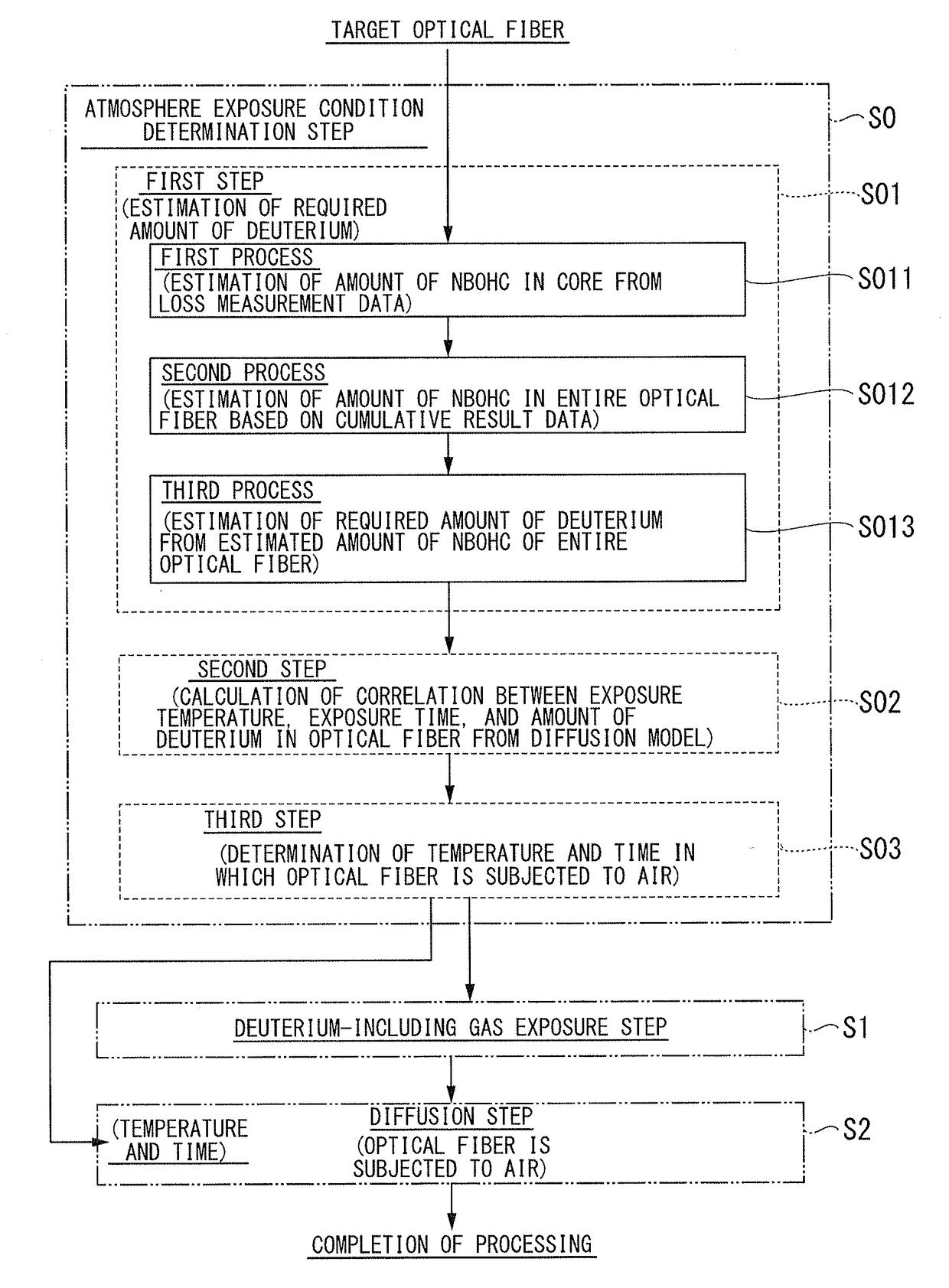
a technology of optical fiber and optical fiber, applied in the direction of optical apparatus testing, instruments, manufacturing tools, etc., can solve the problem that the effect of improving the hydrogen characteristics cannot be sufficiently obtained, and achieve the effect of simple and easy estimation, reduced cost, and reduced overall processing tim

Active Publication Date: 2018-03-20
FUJIKURA LTD
View PDF14 Cites 1 Cited by
  • Summary
  • Abstract
  • Description
  • Claims
  • Application Information

AI Technical Summary

Benefits of technology

This approach significantly shortens the total processing time, prevents excessive deuterium retention, and maintains optimal hydrogen characteristics by accurately estimating and supplying the necessary deuterium amount, thereby improving the long-term transmission loss characteristics of optical fibers.

Problems solved by technology

Because of this, even in the case of raising the temperature, unless the temperature is set to a suitable temperature, deuterium is quickly diffused into the outside of the optical fiber and is removed therefrom, and the effect of improvement in the hydrogen characteristics cannot sufficiently be obtained.

Method used


Image

  • Method of processing optical fiber
  • Method of processing optical fiber
  • Method of processing optical fiber

Examples


example 1

[0142]In Example 1, deuterium is used as an oxygen bridging element.

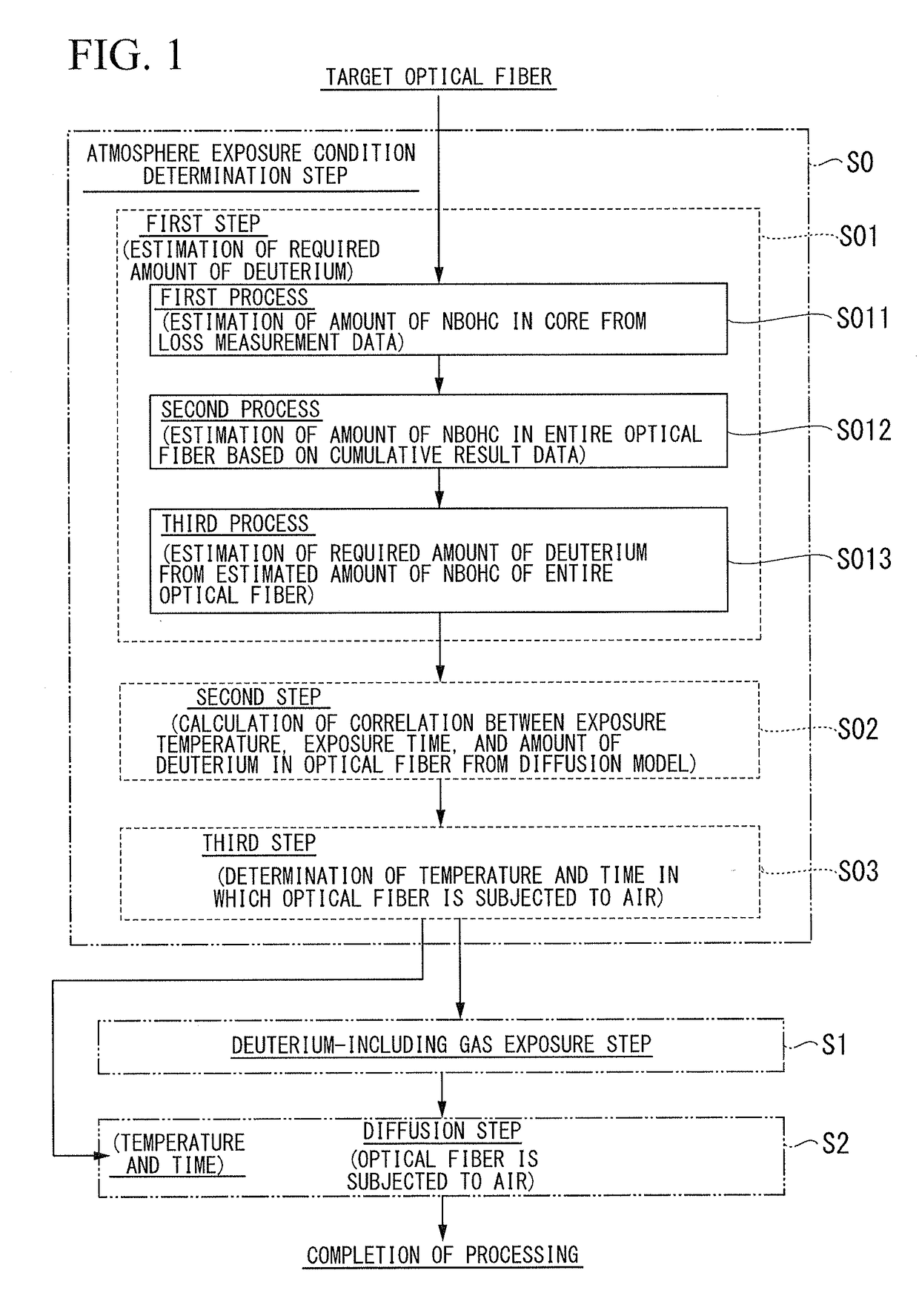
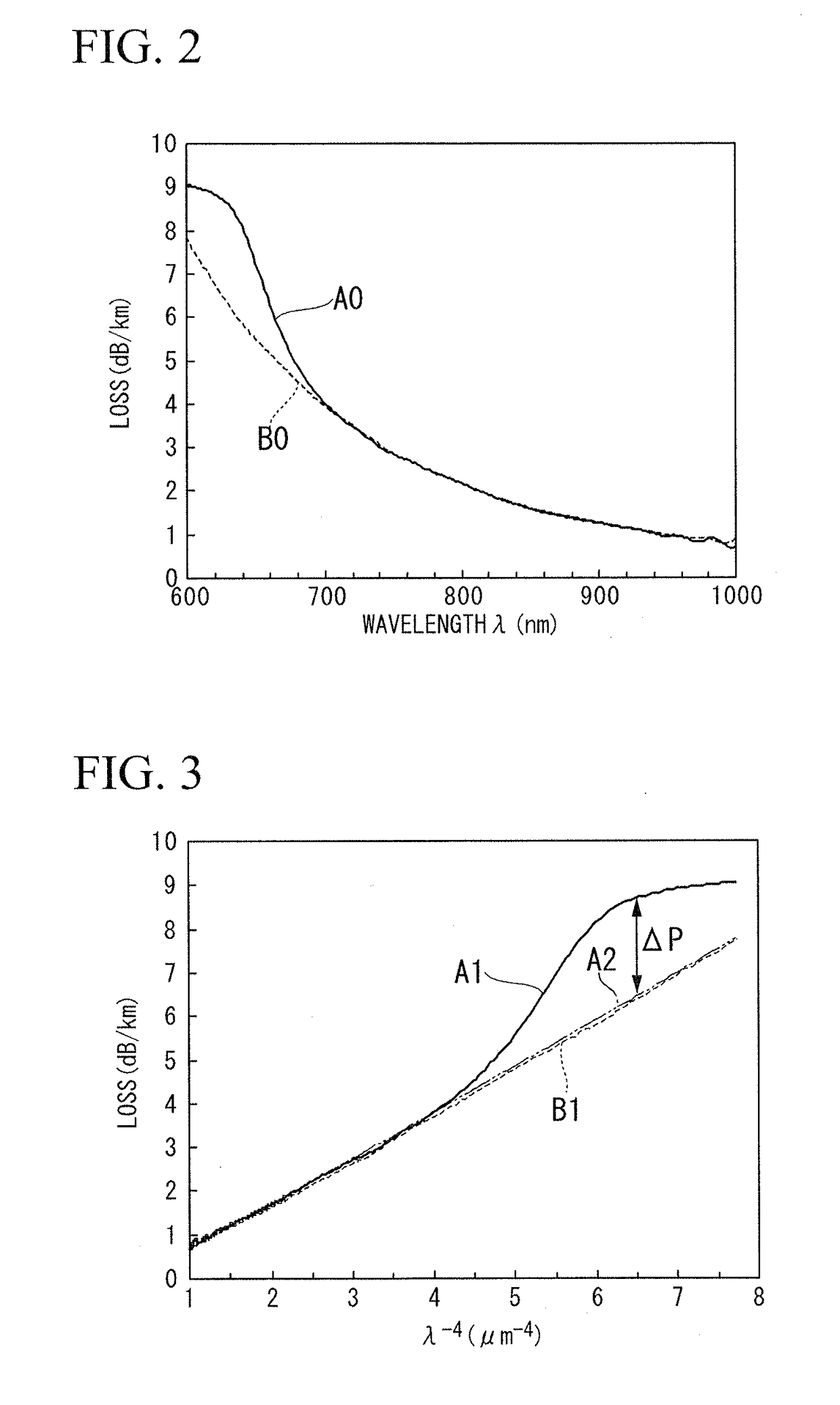
[0143]An optical fiber preform which is made of silica-based glass and is formed by using a vapor-phase axial deposition method and an outside vapor deposition method was subjected to fiber drawing, the drawn fiber was coated with a resin coating made of a ultraviolet curable resin, and therefore a single-mode optical fiber having a glass diameter of 125 μm, a coating diameter of 250 μm, and a length of 50 km was manufactured. The core diameter of the optical fiber was 10 μm. From the optical fiber, a 1 km-length optical fiber was extracted, and the loss characteristics thereof were examined using a short wavelength light source and a spectrum analyzer. A loss at the short-wavelength at wavelengths of 600 nm to 1000 nm was measured and the results shown in the solid line A0 in FIG. 2 was obtained.

[0144]The measurement result indicated by the solid line A0 shown in FIG. 2 includes both a loss due to Rayleigh scatteri...


PUM

PropertyMeasurementUnit
wavelengthaaaaaaaaaa
temperatureaaaaaaaaaa

Abstract

A method of processing an optical fiber of the invention includes: a determination step of determining at least an ambient temperature of conditions of a diffusion treatment that causing an optical fiber to be subjected to an non-oxygen bridging atmosphere; an exposure step of exposing the optical fiber to a gas including an oxygen bridging element that is capable of processing the Non-Bridging Oxygen Hole Centers by being bonded to a non-bridging oxygen in the optical fiber, and causing the oxygen bridging element to infiltrate into the optical fiber; and a diffusion step of subsequently causing the optical fiber to be subjected to the non-oxygen bridging atmosphere in the exposure ambient temperature which is determined by the determination step and at which the optical fiber is subjected to the non-oxygen bridging atmosphere, and thereby diffusing the oxygen bridging element into the optical fiber.

Description

CROSS-REFERENCE TO RELATED APPLICATION[0001]This application is based on and claims priority from Japanese Patent Application No. 2014-139913 filed on Jul. 7, 2014, the contents of which are incorporated herein by reference in their entirety.BACKGROUND OF THE INVENTION[0002]Field of the Invention[0003]The present invention relates to a processing method of improving long-term transmission loss characteristics (hydrogen characteristics) due to Non-Bridging Oxygen Hole Centers (NBOHC) in an optical fiber after drawing a silica-based optical fiber. Particularly, the present invention relates to a method of determining the temperature at which an optical fiber is left in air in the processing method and an estimation method of optimally estimating the amount of an oxygen bridging element (deuterium or hydrogen) necessary for processing NBOHC in the processing method.[0004]Description of the Related Art[0005]Generally, in a step of drawing an optical fiber using a silica-based glass, a g...

Claims


Application Information

Patent Timeline
Patent Type & Authority Patents(United States)
IPC IPC(8): C03C25/60C03C13/04C03C25/10G01M11/00C03B37/01G02B6/02
CPCC03C25/607C03B37/01C03C13/047C03C25/106G02B6/02G01M11/30Y02P40/57C03B2201/22C03C2201/22C03C2203/54
Inventor HAMAGUCHI, HIROKI
Owner FUJIKURA LTD
Learn More