

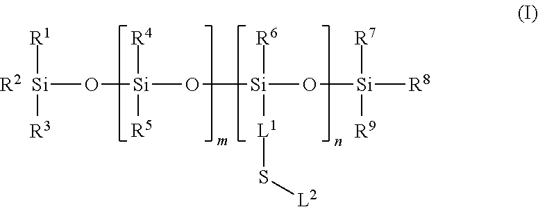
Silicone ligands for quantum dots
a technology of quantum dots and ligands, applied in the field of silicon polymer ligands, can solve the problems of poor color rendering, poor power efficiency, and number of critical shortfalls
- Summary
- Abstract
- Description
- Claims
- Application Information
AI Technical Summary
Benefits of technology
Problems solved by technology
Method used
Image

Examples
example 1
Preparation of a Lower MW Succinic Acid Silicone Ligand
[0316]
[0317]To a 20 mL vial of allyl succinic acid (0.439 g, 2.78 mmol) was added 2 mL toluene and the mixture was heated to dissolve at 84° C. In a separate vial was added 5.00 g (8.33 mmol of SH) of mercapto functional silicone fluid GP-367 (Genesse Polymers Corporation, Burton Mich.) with heating to 84° C. The hot silicone solution was added to the allyl succinic acid solution with rapid stirring and was immediately followed by the addition of 0.015 g of Vazo® 88 initiator (DuPont, Wilmington, Del.) pre-dissolved in 0.5 mL of toluene. The reaction continued to be heated at 84° C. After 5 minutes, 0.144 g (1.25 mmol) of allyltrimethylsilane was added. An NMR sample at 20 minutes showed 50% allyl succinic acid remaining. An additional 0.43 g (2.99 mmol) of allyltrimethylsilane was added. After 60 minutes, a NMR sample showed 10% allyl succinic acid remaining After 3 hours, an additional 0.43 g (2.99 mmol) of allyltrimethylsilan...
example 2
Preparation of a Higher MW Succinic Acid Silicone Ligand
[0318]
[0319]The preparation of the higher MW succinic acid silicone ligand follows the procedure of Example 1 using 0.20 equivalents of allyl succinic acid and 0.47 equivalents per chain of cyclohexane divinylether followed by the addition of an excess amount of allyltrimethylsilane. The MW of the resultant product was about 8200.
example 3
Compositions of Quantum Dots with Lower MW Succinic Acid Silicone Ligand
[0320]Ligand exchange was accomplished by dissolving InP quantum dots in hexane or toluene, adding the lower MW succinic acid silicone ligand, heating at 50° C. to 60° C. for 16 hours to 36 hours, and removing the volatiles by vacuum transfer. The quantum yield and other parameters were maintained, and the nanocrystals were left in silicone as a clear oil. Exchanges with InP quantum dot solutions with lower MW succinic acid silicone ligands lots is provided in TABLE 1. As shown in TABLE 1, quantum yield (QY) is maintained and the wavelength (WL) and full width at half maximum (FWHW) are not significantly impacted with the various lots. And, as shown in TABLE 1, quantum yield is preserved, with some variability, in the exchange of DDSA (2-Dodecen-1-yl)-succinic acid to the silicone succinic acid polymer. Non-DDSA exchanged InP quantum yield increased 4.6% over the octadecene shell solution.
[0321]
TABLE 1Silicone E...
PUM
| Property | Measurement | Unit |
|---|---|---|
| temperature | aaaaa | aaaaa |
| temperature | aaaaa | aaaaa |
| temperature | aaaaa | aaaaa |
Abstract
Description
Claims
Application Information