Method and apparatus for conducting real-time process control of particle and fiber generation
a technology of process control and particle and fiber, which is applied in the direction of instruments, measurement devices, textiles and paper, etc., can solve the problem of not being able to analyze fibers in real time as they form
- Summary
- Abstract
- Description
- Claims
- Application Information
AI Technical Summary
Benefits of technology
Problems solved by technology
Method used
Image
Examples
example 1
me Fraction Verification
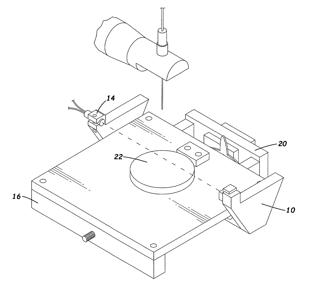
[0030]Since soot volume fraction measurement methods utilizing laser scattering and the Beer-Lambert law are used with the tool of the subject invention, a tea-candle was placed within the scanning field to verify its operation. The scanning step size was approximately 2 mm per step, with 15 voltage measurements per step. By reducing the air flow around the candle, the flame was reasonably stabilized for the measurement process.
[0031]FIG. 4 is the plot of the voltage that was reported from the 10-bit ADC that is contained in the microcontroller. The noise level shown has an approximate magnitude of 7 mV. The magnitude of the signal voltage is approximately 30 mV with an initial deflection point at collection point 7 and a final deflection point at collection point 13. FIG. 5 is a plot of the soot volume fraction as it was calculated using the described methods. The results show that a higher concentration (approximately 132 ppb) of soot particles is measured ...
example 2
inning Experimentation with Poly(Vinyl Alcohol)
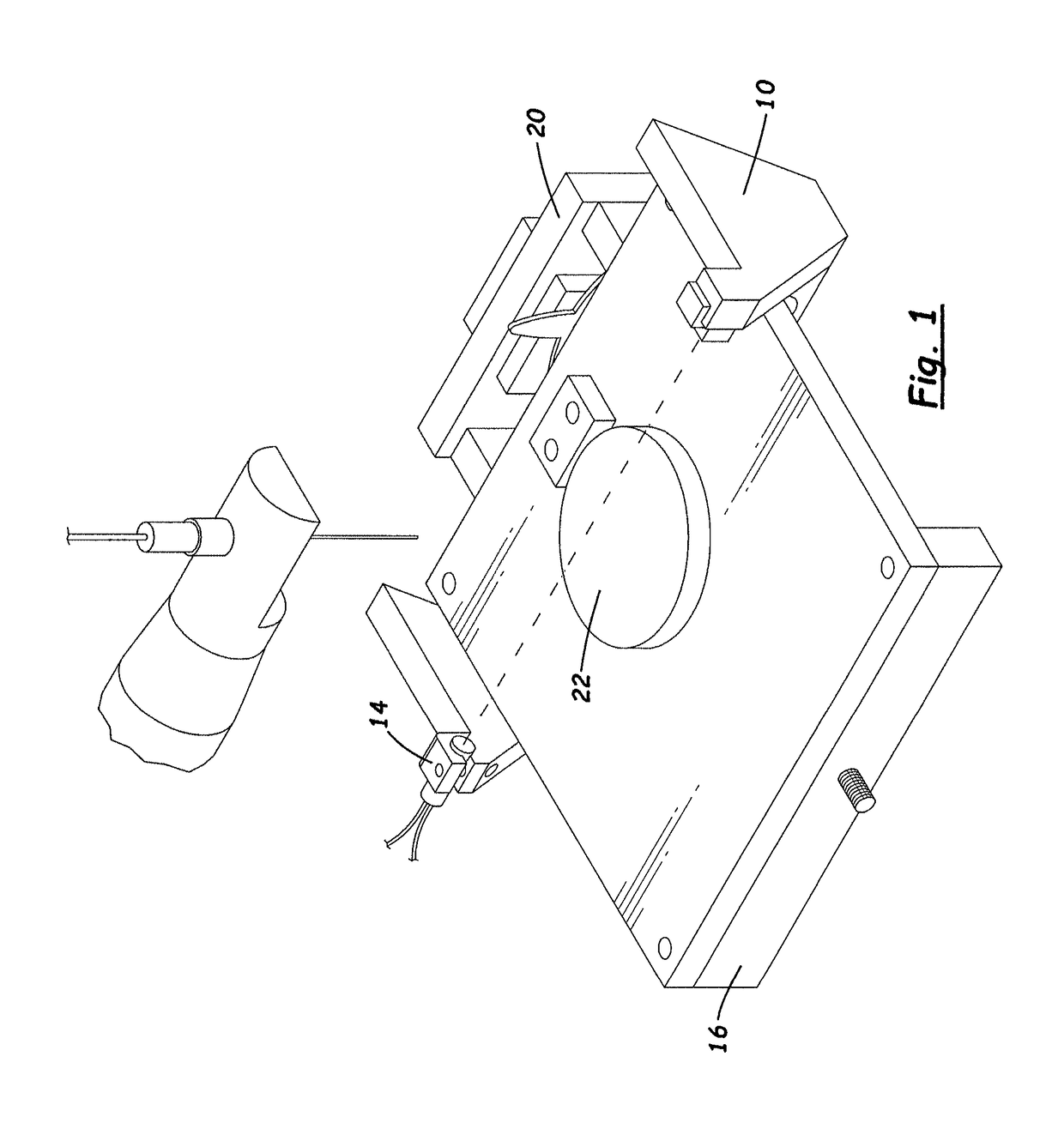
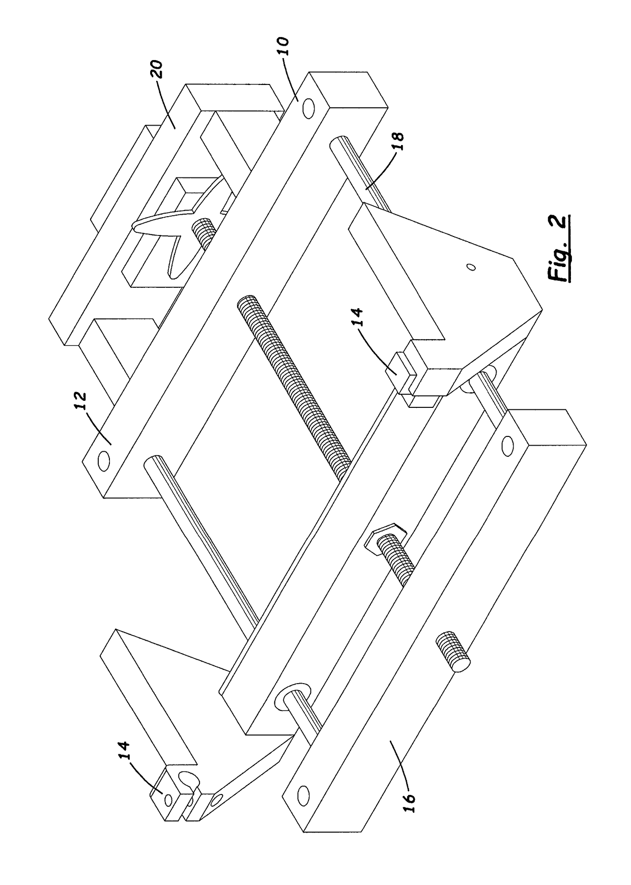
[0032]The exemplified embodiment of the tool of the subject invention was installed in the SPRAYBASE® electrospinner to scan through the electrospun fiber deposition field. The SPRAYBASE® was setup to achieve stable electrospinning with a 4 wt % Poly(vinyl alcohol) solution. A needle to collection plate separation distance of 4 cm was used throughout the process. The voltage potential was set to 10.5 kV and 0.027 bar of pressure was applied to the solution for fluid delivery. The laser / sensor assembly was moved through the electrospun fiber deposition field while fibers were being deposited onto a conductive substrate. The tool collected 10 data points through the deposition area. At each data point the tool collected 15 intensity measurements, as measured through the voltage output of the photodiode, and averaged the intensity to reduce the amount of noise that affected the process. The voltages were then compared to tool noise measure...
example 3
inning Experimentation with Poly(Ethylene Oxide)
[0034]Following the example set forth in Example 2; stable electrospinning was achieved with an 8 wt % Poly(ethylene oxide) solution. A needle to collection plate separation distance of 4.5 cm was used with a voltage potential of 6 kV and a flow rate of 0.003 mL / hr through a 20 gauge capillary. The tool collected intensity measurements at a rate of 100 samples per second (sps). Without stopping the electrospinning deposition, the tool was manually moved through the deposition to a point outside of the deposition field then returned to the starting point of the scan (FIG. 8). The same trend of deflection observed in Example 2 was observed in Example 3 when sampling at 100 sps through Poly(ethylene oxide) (FIG. 8). When sampling with an ADC, filtering is needed. A 25th order median filter and a 5th order moving average filter are used to filter out outliers and discretizing errors.
[0035]The soot volume fraction date verified use of the t...
PUM
| Property | Measurement | Unit |
|---|---|---|
| wavelength | aaaaa | aaaaa |
| voltage | aaaaa | aaaaa |
| voltage | aaaaa | aaaaa |
Abstract
Description
Claims
Application Information
 - R&D
- Intellectual Property
- Life Sciences
- Materials
- Tech Scout
- Unparalleled Data Quality
- Higher Quality Content
- 60% Fewer Hallucinations
Browse by: Latest US Patents, China's latest patents, Technical Efficacy Thesaurus, Application Domain, Technology Topic, Popular Technical Reports.
© 2025 PatSnap. All rights reserved.Legal|Privacy policy|Modern Slavery Act Transparency Statement|Sitemap|About US| Contact US: help@patsnap.com


