Reduction of cold-start emissions and catalyst warm-up time with direct fuel injection

a technology of direct fuel injection and catalyst, which is applied in the direction of electric control, ignition automatic control, machines/engines, etc., can solve the problems of insufficient temperature of catalyst material in the catalytic converter in order to sufficiently process the unwanted, uncombusted, by-products of combustion, and inhibit the proper vaporization of fuel. , to achieve the effect of reducing hydrocarbons

Inactive Publication Date: 2000-06-20
FORD GLOBAL TECH LLC
View PDF12 Cites 44 Cited by
  • Summary
  • Abstract
  • Description
  • Claims
  • Application Information

AI Technical Summary

Benefits of technology

It is an object of the present invention to reduce hydrocarbons produced during cold start of a spark ignited internal combustion engine by

Problems solved by technology

The temperature of the intake passages and the combustion chambers of the engine during the early stages of a cold start inhibit the proper vaporization of fuel.
As a result, during cold start, a stoichiometric air / fuel ratio is difficult to achieve with intake port fuel injection.
During the early stages of a cold start, the catalyst material in the catalytic converter has not reached a sufficient temperature in order to sufficiently process the unwanted, and uncombusted, by-products of combustion.
Unfortunately, use of the EHC adds additional cost, extra complexity, and requires a delay prior to engine starting to allow the EHC to preheat the catalyst.
However, Sasaki et al. do not contemplate reduction of hydrocarbon emissions by achieving immediate combustion as quickly as possible upon cold start.
Thus, the approach contemplated by Sasaki et al. has limited use in cold start of an engine.

Method used


Image

  • Reduction of cold-start emissions and catalyst warm-up time with direct fuel injection
  • Reduction of cold-start emissions and catalyst warm-up time with direct fuel injection

Examples


Embodiment Construction

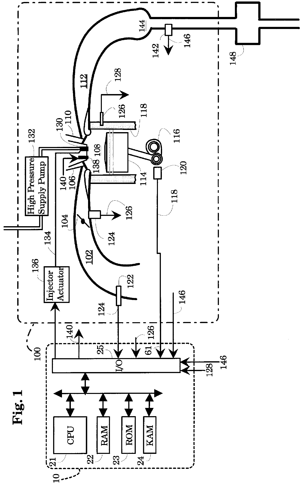
FIG. 1 of the drawings shows an Electronic Engine Controller (EEC) 10 and an internal combustion engine 100, which comprises a plurality of cylinders, one of which is shown in FIG. 1. Engine 100 draws an aircharge through an intake manifold 102, past a throttle plate 104, and intake valve 106 and into combustion chamber 108. An air / fuel mixture which consists of the aircharge and fuel injected by fuel injector 130, is ignited in combustion chamber 108, and exhaust gas produced from combustion of the air / fuel mixture is transported past exhaust valve 110 through exhaust manifold 112. A piston 114 is coupled to a crankshaft 116, and moves in a linear fashion within a cylinder defined by cylinder walls 118.

A crankshaft position sensor 120 detects the rotation of crankshaft 116 and transmits a crankshaft position signal 118 to EEC 10. Crankshaft position signal 118 preferably takes the form of a series of pulses, each pulse being caused by the rotation of a predetermined point on the cr...


PUM


Abstract

An internal combustion engine employs fuel injectors positioned to inject fuel directly into combustion chambers of the engine, and an electronic engine controller (EEC) to control operation of the engine. The EEC implements a cold start routine which controls the amount of fuel injected, the time at which the fuel is injected and spark timing to achieve a rapid increase in temperature of the engine and the exhaust system components, thereby decreasing tailpipe hydrocarbon emissions during cold start.

Description

FIELD OF THE INVENTIONThis invention relates to the field of electronic engine control and more particularly to the field of reducing hydrocarbon emissions during cold start in a spark ignited internal combustion engine which employs direct fuel injection.BACKGROUND OF THE INVENTIONA disproportionately large amount of the hydrocarbons produced by a vehicle are emitted during cold starting of the vehicle engine. The temperature of the intake passages and the combustion chambers of the engine during the early stages of a cold start inhibit the proper vaporization of fuel. As a result, during cold start, a stoichiometric air / fuel ratio is difficult to achieve with intake port fuel injection. In addition, unburned fuel vapor is delivered to the catalytic converter together with the normal by-product of combustion. During the early stages of a cold start, the catalyst material in the catalytic converter has not reached a sufficient temperature in order to sufficiently process the unwante...

Claims


Application Information

Patent Timeline
Patent Type & Authority Patents(United States)
IPC IPC(8): F01N3/20F02D37/00F02D37/02F02D41/02F02D41/06F02D41/40F02P5/15F02D41/34
CPCF01N3/20F01N3/2006F02D37/02F02D41/024F02D41/0255F02D41/345F02D41/405F02P5/1506F02D41/064F01N2430/06Y02T10/26F02D2041/389Y02T10/46Y02T10/44Y02T10/12Y02T10/40
Inventor BREHOB, DIANA DAWNANDERSON, RICHARD WALTERYANG, JIALINWHITEAKER, ROBERT MICHAEL
Owner FORD GLOBAL TECH LLC
Why Eureka
Try Eureka