Method and apparatus for drying bearing

a technology for bearings and drying methods, applied in the direction of drying machines with progressive movements, drying solid materials without heat, cleaning using liquids, etc., can solve the problems of reducing bearing manufacturing productivity, reducing bearing production efficiency, and reducing the production efficiency of bearings, so as to achieve the effect of reducing the drying process, and reducing the drying tim

Inactive Publication Date: 2000-08-01
NSK LTD
View PDF18 Cites 8 Cited by
  • Summary
  • Abstract
  • Description
  • Claims
  • Application Information

AI Technical Summary

Benefits of technology

According to the present invention, an object to be rinsed which is complicated in configuration and small in size can be degreased and dried completely and quickly without using any organic solvent by putting the object rinsed with a hydrocarbon cleaning agent in the hermetic container and by evacuating the air in the hermetic container.
More specifically, the vapor pressure of the hydrocarbon cleaning agent increases when the air in the hermetic container is evacuated and the boiling point of the hydrocarbon cleaning agent sticking to the rinsed object becomes lower than its boiling point at atmospheric pressure. Consequently, the hydrocarbon cleaning agent is easier to vaporize than at atmospheric pressure. The rinsed object can thus be degreased and dried completely and quickly as the degreasing and drying process is considerably accelerated.
Moreover, various problems heretofore originating from the use of organic solvents can thoroughly be solved since no organic solvents are used and cost reduction is made possible by the vacuum degreasing-drying method according to the present invention.
Furthermore, it is also possible to improved degreasing-drying efficiency by heating the object in the hermetic container using such an infrared heater, a high-frequency heater or the like.

Problems solved by technology

Nonetheless, the growing tendency is for the use of freon gas, 1, 1, 1-trichloroethane and the like to be increasingly restricted worldwise in order to protect the ozone layer.
The water stored in this portion tends to increase the time to dry the bearing, thus decreasing bearing manufacturing productivity, rendering difficult the continuous production of bearings and so on.
If, otherwise, the method of blowing hot air at the bearing rinsed with an aqueous solvent such as a water or irradiating it with an infrared ray is used, the resulting heat may badly affect a plastic portion such as a retainer or the bearing itself, or may cause the bearing to gather rust, though the drying period is shortened.
In addition, the method of mechanically wiping off moisture sticking to such a bearing by means of, for instance, a dehydrator still poses a problem in that no effect is actually accomplishable effectively.
Further, as conventional methods for degreasing and drying extremely small, precision metal products and the like complicated in configuration after they have been rinsed with a hydrocarbon cleaning agent, those generally used employ, for instance, chlorine organic solvents such as freon and 1, 1, 1-trichloroethane which are highly volatile at the normal temperature, alcoholic organic solvents such as ethanol, highly volatile petroleum hydrocarbon such as gasoline and petroleum benzine, and chemical compound organic solvents such as benzine, hexane and toluene after a hydrocarbon rinsing process.
Notwithstanding the above, the use of such freon, 1, 1, 1-trichloroethane and the like has been restricted because they cause great destruction of the ozone layer.
Moreover, low inflammable organic solvents need to satisfy complete explosion-proof specifications as they are under rigid restrictions due to the fire laws and the use of them costs a great deal.
As a result, a number of problems arise when organic solvents are used because the poisoning preventive regulations are applied to the organic solvents, for instance.
Therefore, efforts may be attempted to degrease and dry extremely small, precision metal products without using the aforementioned organic solvents; however, the problems is that it is still impractical to do so because a great deal of time is consumed for drying and because productivity is considerably reduced.
When some of the hydrocarbon cleaning agent is left on the surface of such an extra-small diameter, miniature bearing and its parts as it has been dried incompletely, for instance, the application of grease thereto at the following process step may result in lowering the viscosity of the grease, thus causing grease leakage and the spread of the hydrocarbon cleaning agent.
In addition to these problems, the acoustic quality of the bearing may deteriorate or the bearing may fail to come in contact with the shaft of a HDD spindle (hard disk drive spindle) motor or the housing, which may cause dust to gather therein.

Method used


Image

  • Method and apparatus for drying bearing
  • Method and apparatus for drying bearing
  • Method and apparatus for drying bearing

Examples


second embodiment

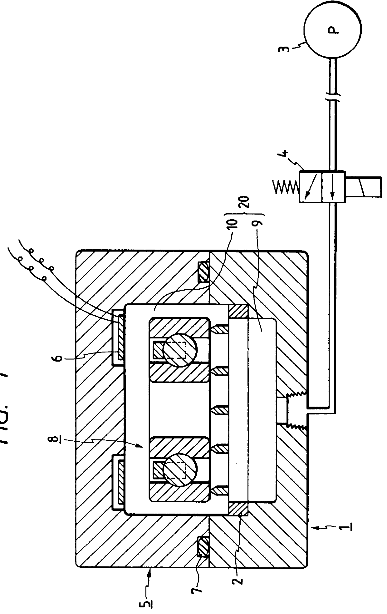
FIG. 3 is a sectional view of a drying apparatus of the present invention, wherein the apparatus similar to what is shown in FIG. 1 is equipped with a choke device and a filter.

In the drying apparatus of FIG. 3, the upper mold 5 of what is shown in FIG. 1 is supplied with a choke device 51 communicating with the internal space 10 thereof and the choke device 51 is connected via piping 50 to a filter 52, whereby air can circulate through the internal space 20 of the hermetic container.

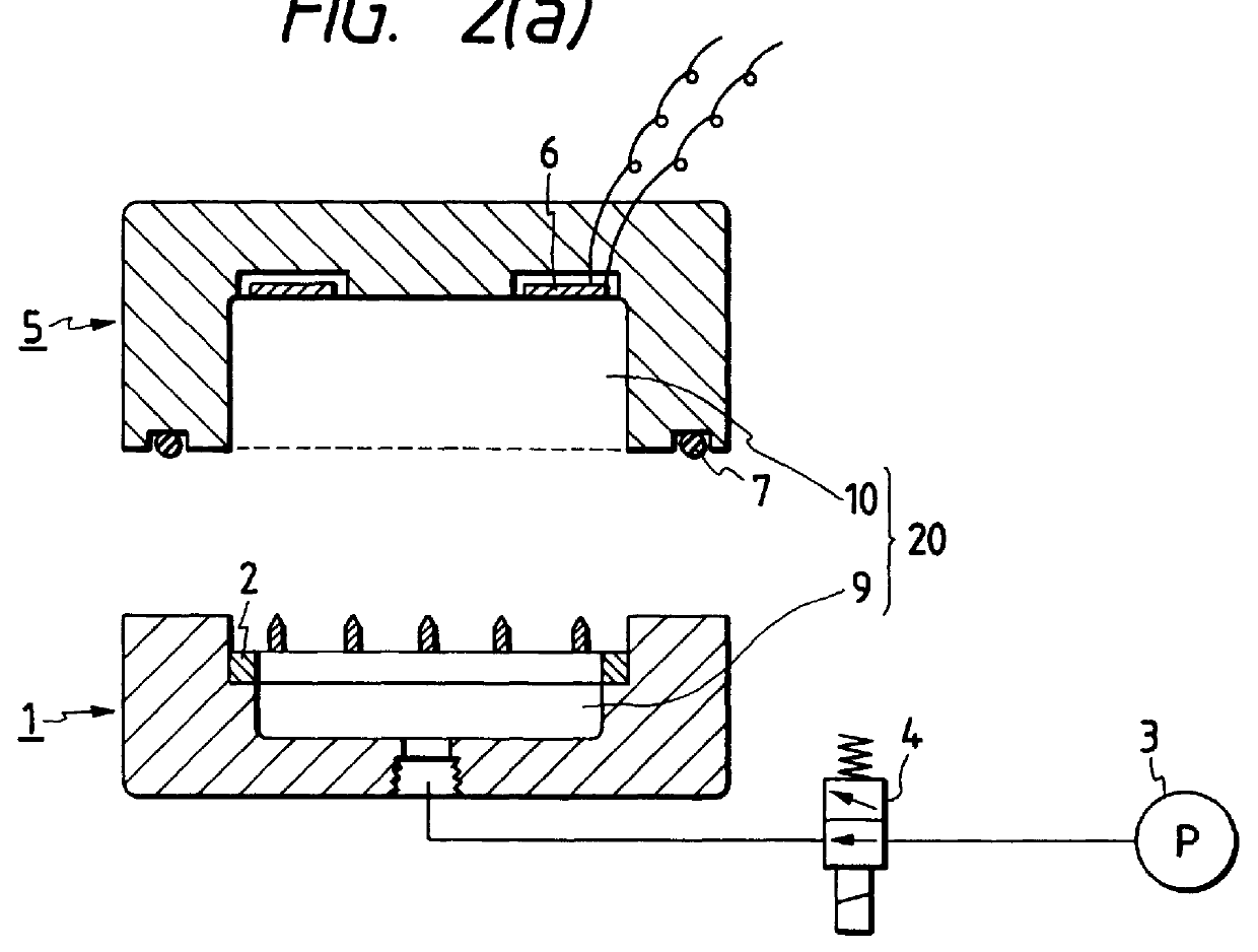
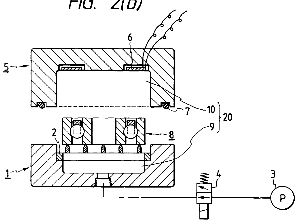
Until the lower mode 1 is separated from the upper mold 5 on the termination of reducing the pressure in the internal space 20 of the hermetic container at the step of FIG. 2(d) after the reduction of the pressure therein is started at the step of FIG. 2(c), the choke device 51 operates to regulate the flow rate of clean air passing through the filter 52 and the air is introduced into the internal space 20 of the hermetic container. Saturated vapor existing in the internal space 20 of the hermetic conta...

third embodiment

FIG. 4 is a sectional view of a drying apparatus of the present invention, wherein instead of the high-frequency heater 6 of the drying apparatus of FIG. 1, an infrared heater 53 is employed.

The use of such an infrared heater 53 makes radiation heating possible.

fourth embodiment

FIG. 5 is a sectional view of a drying apparatus of the present invention, wherein a piping part, a solenoid valve and an oil mist lubricator are provided for the upper mold of the apparatus similar to what is shown in FIG. 1 and wherein an additional solenoid valve is also provided for the lower mold thereof.

The upper mold 5 of the drying apparatus of FIG. 5 similar to what is shown in FIG. 1 is equipped with a piping part 54 in such a way as to communicate with the internal space 10 of the upper mold and a solenoid valve 55 is connected via piping 50 to the piping part 54. Further, the solenoid valve 55 is consecutively connected to an oil mist lubricator 56 loaded with rust preventive oil. The rust preventive oil is introduced into the internal space 20 of the hermetic container and made to stick to the workpiece 8 therein. An additional solenoid valve 57 is connected to the lower mold 1, thus allowing air to circulate from the outside to the internal space 20 of the hermetic con...


PUM


Abstract

In order to provide a vacuum degreasing-drying method by which extremely small, precision metal products can be degreased and dried quickly and completely without using organic solvents, according to the present invention, an object 112 to be rinsed is put in a vacuum drier 110 after being rinsed with a hydrocarbon cleaning agent and then the air in the vacuum drier 110 is evacuated so as to degrease and dry the object thus rinsed.

Description

BACKGROUND OF THE INVENTIONThe present invention relates to a method and apparatus for drying bearings, especially those conveyed on a production line after being rinsed with an aqueous solvent such as a water. Further, the present invention also relates generally to a vacuum degreasing-drying methods and more particularly to a vacuum degreasing-drying method for degreasing and drying extremely small, precision metal products, especially extra-small diameter miniature bearings and their parts after they have been rinsed with a hydrocarbon cleaning agent.A method of the sort that has heretofore been employed for drying metal bearings, especially those complicated in configuration, after being rinsed with an aqueous solvent such as water normally comprises the steps of removing moisture sticking to the surface of the bearing, and drying it by the use of organic solvents such as Freon gas and 1, 1, 1-trichloroethane.Methods other than what has been mentioned above include drying the be...

Claims


Application Information

Patent Timeline
Patent Type & Authority Patents(United States)
IPC IPC(8): F26B5/04B08B3/08
CPCF26B5/048
Inventor SATO, CHUICHIKIKUCHI, AKIRASAITO, HIROSHITAKAIRA, SHINICHI
Owner NSK LTD
Why Eureka
Try Eureka