Scanning exposure apparatus

a technology of exposure apparatus and scanning lens, which is applied in the direction of photomechanical apparatus, instruments, printing, etc., can solve the problems of difficult design and manufacture to realize both the high resolution and wide field of projection optical system, and difficulty in reducing exposure amount, so as to reduce the unevenness of exposure amount in the non-scanning direction.

Inactive Publication Date: 2001-08-07
NIKON CORP
View PDF11 Cites 61 Cited by
  • Summary
  • Abstract
  • Description
  • Claims
  • Application Information

AI Technical Summary

Benefits of technology

When a one-dimensional pivot mirror (e.g., a polygonal mirror or a galvano mirror) for moving the interference fringes in only the scanning direction is used as the variable phase member, the pivot control of the pivot mirror can be realized by simple reciprocal motion if the direction (sign) of the moving amount in the relative scanning direction of the interference sc

Problems solved by technology

As a result evenness of the illuminance on the reticle and wafer is impaired.
However, it is very difficult in terms of design and manufacture to realize both the high resolution and wide field of the projection optical system.
Therefore

Method used


Image

  • Scanning exposure apparatus
  • Scanning exposure apparatus
  • Scanning exposure apparatus

Examples


first embodiment

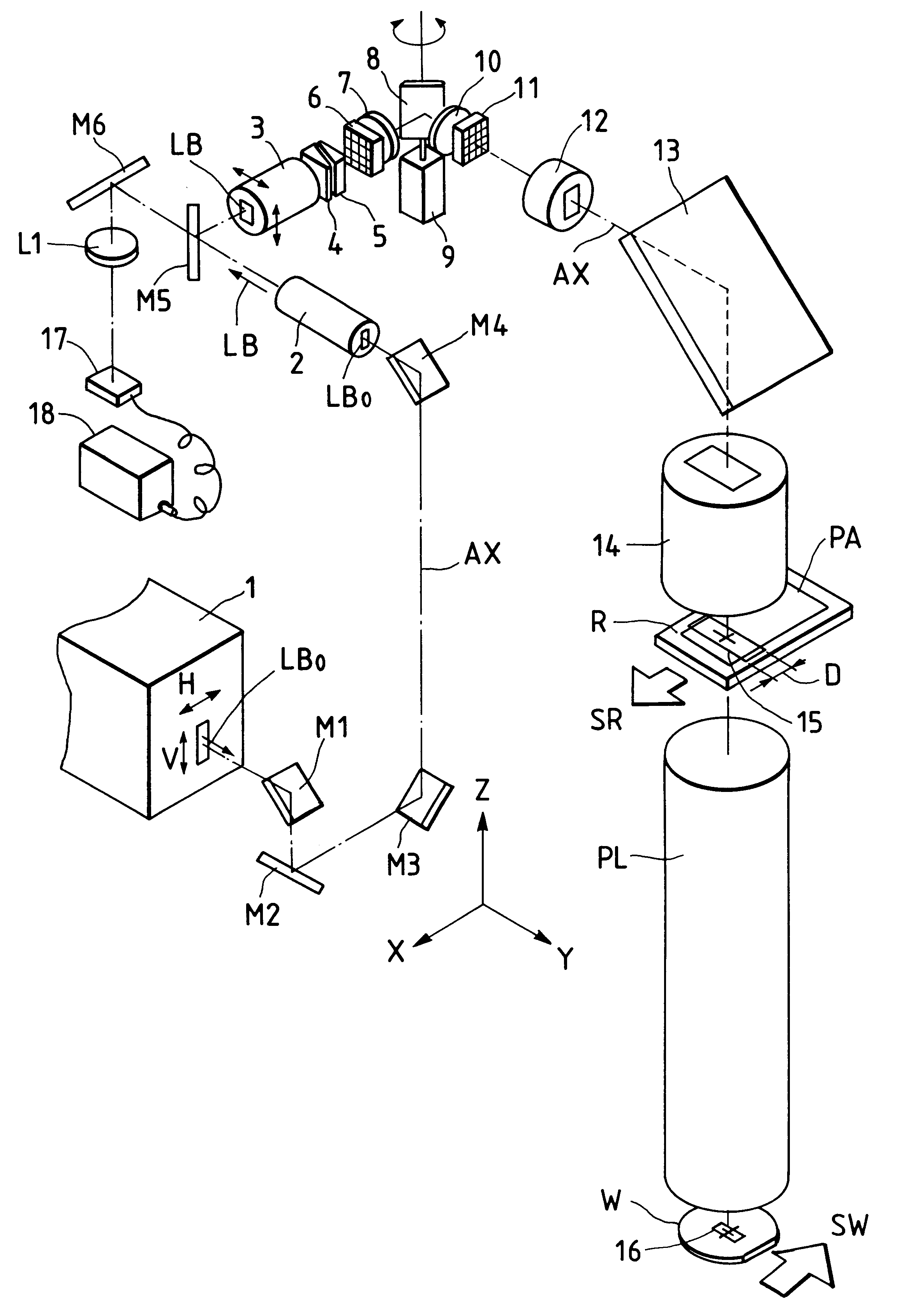
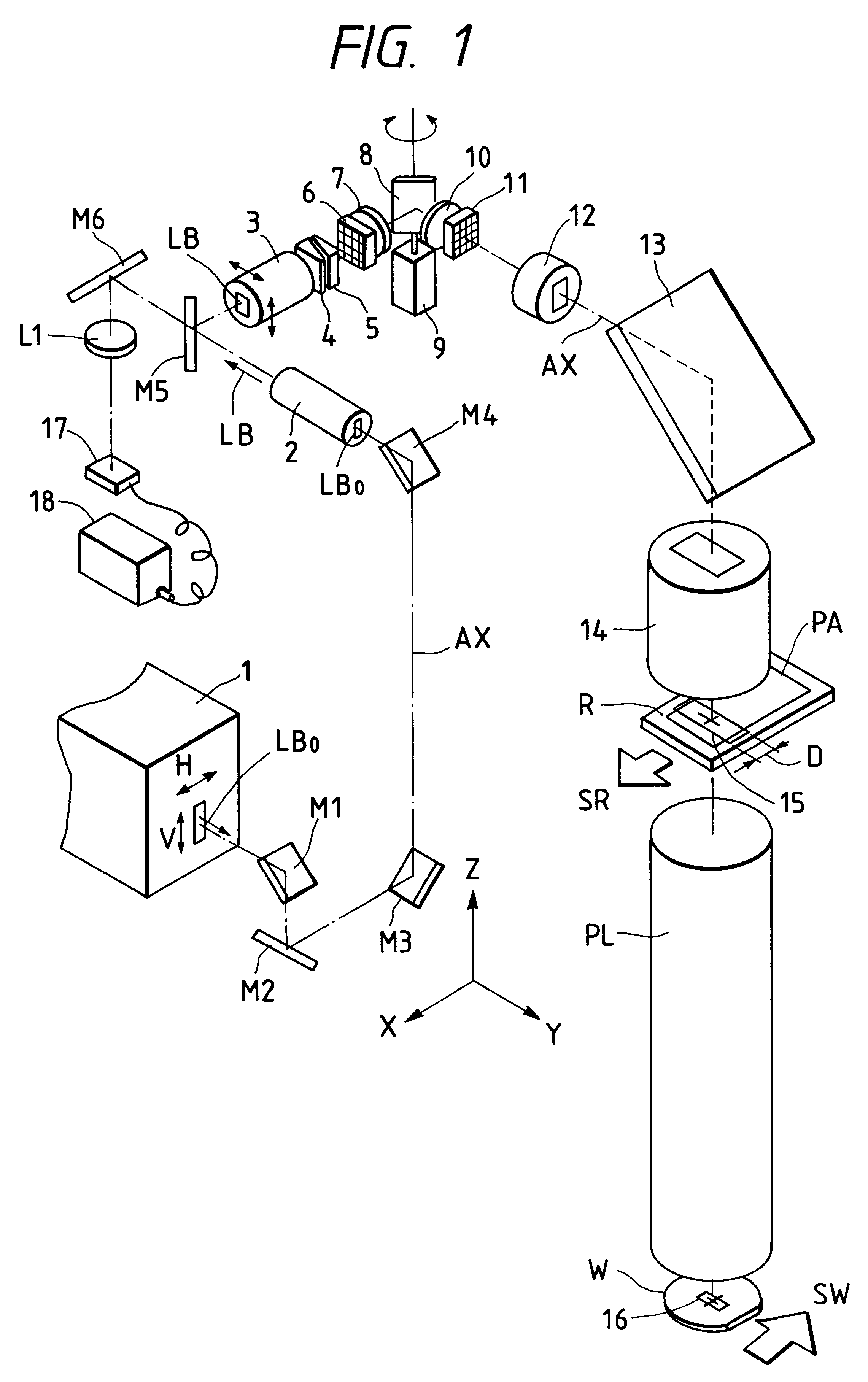
the present invention will be described below with reference to FIG. 1 to FIGS. 6A and 6B. In this embodiment, the present invention is applied to a step-and-scan type scanning exposure apparatus which comprises a pulse oscillation type laser light source.

Referring to FIG. 1, a laser beam LB.sub.0 in a far ultraviolet range (e.g., a wavelength of 248 nm) emitted from an excimer laser light source 1 is incident on a beam shaping optical system 2, including cylindrical lenses, via mirrors M1, M2, M3, and M4. The sectional shape of the laser beam LB.sub.0 emitted from the excimer laser light source 1 is an elongated rectangular shape in which the dimension in the horizontal direction (H direction) is considerably smaller than that in the vertical direction (V direction). The beam shaping optical system 2 expands the dimension in the horizontal direction of the laser beam LB.sub.0, and outputs a laser beam LB with a sectional shape having substantially the same aspect ratio (almost simi...

second embodiment

the present invention will be described below with reference to FIG. 7. FIG. 7 shows the arrangement of a scanning projection exposure apparatus according to the embodiment comprising a pulse oscillation type laser light source. The same reference numerals in FIG. 7 denote parts having the same functions and effects as those in FIG. 1.

Referring to FIG. 7, a laser beam LB.sub.0 in a far (or deep) ultraviolet range (e.g., a wavelength of 248 nm) emitted from an excimer laser light source 1 is incident on a beam shaping optical system 2 including cylindrical lenses. In general, the sectional shape of the laser beam LB.sub.0 emitted from the excimer laser light source 1 is an elongated rectangular shape in which the dimension in the horizontal direction (H direction) is considerably smaller than that in the vertical direction (V direction). The beam shaping optical system 2 shapes the laser beam LB.sub.0 into a beam which has a square section with an aspect ratio of 1 : 1, and outputs t...


PUM


Abstract

A projection exposure apparatus for transferring a pattern formed on a mask onto a photosensitive substrate by a scanning exposure method, includes a light source for generating a light beam having a predetermined spatial coherence, an illumination optical system for receiving the light beam from the light source and illuminating a local area on the mask with the light beam, and a device for synchronously moving the mask and the photosensitive substrate so as to transfer the pattern on the mask onto the photosensitive substrate. A direction, corresponding to a higher spatial coherence of the light beam, is made to coincide with the direction of relative scanning an illumination area and the mask in the illumination area.

Description

BACKGROUND OF THE INVENTION1. Field of the InventionThe present invention relates to a scanning exposure apparatus, used in a photolithography process in the manufacture of, e.g., a semiconductor element, a liquid crystal display element, a thin-film magnetic head, or the like, for transferring a pattern on a mask onto a substrate by synchronously moving the mask (or reticle) and the substrate and, more particularly, to a scanning exposure apparatus suited for a case wherein light having a high spatial coherency (e.g., harmonics of a KrF or ArF excimer laser, YAG laser, or the like) is used.2. Related Background ArtIn the photolithography process for the manufacture of semiconductor elements, a reduction projection exposure apparatus (stepper) adopting a step-and-repeat method for transferring a pattern on a mask or reticle (to be generally referred to as a "reticle" hereinafter) onto a semiconductor wafer coated with a photosensitive material (photoresist) via a projection optical ...

Claims


Application Information

Patent Timeline
IPC IPC(8): G03F7/20H01L21/027
CPCG03F7/70075G03F7/70358G03F7/70575G03F7/70583H01L21/027
Inventor NAKASHIMA, TOSHIHARUHAMATANI, MASATOOZAWA, KEN
Owner NIKON CORP
Why Eureka
Try Eureka