High frequency pulse transformer for an IGBT gate drive

a high-frequency pulse transformer and gate drive technology, applied in the field of motor control systems, can solve the problems of high controller costs and high usage costs, stage at higher switching frequencies that have proven to be either insolvable or prohibitively costly, and seriously affect the system efficiency, so as to achieve the effect of improving isolation

Inactive Publication Date: 2003-04-22
KOLLMORGEN CORP
View PDF3 Cites 10 Cited by
  • Summary
  • Abstract
  • Description
  • Claims
  • Application Information

AI Technical Summary

Benefits of technology

An object of the present invention is to provide improved isolation between the sensitive electronic stages and the associated power stages.

Problems solved by technology

In the higher horsepower ranges inefficient use of components and inefficient overall system design directly translate into high controller costs and high usage costs.
However, the problems associated with operating the power stages at higher switching frequencies have proven to be either insolvable or prohibitively costly both in space and money.
High frequency noise can bleed off power from the system and seriously affect the system efficiency.
Noise of the common mode variety (noise that goes up and down together on a parallel conductor pair), can be particularly difficult to detect and even more difficult to eliminate.

Method used


Image

  • High frequency pulse transformer for an IGBT gate drive
  • High frequency pulse transformer for an IGBT gate drive
  • High frequency pulse transformer for an IGBT gate drive

Examples


Embodiment Construction

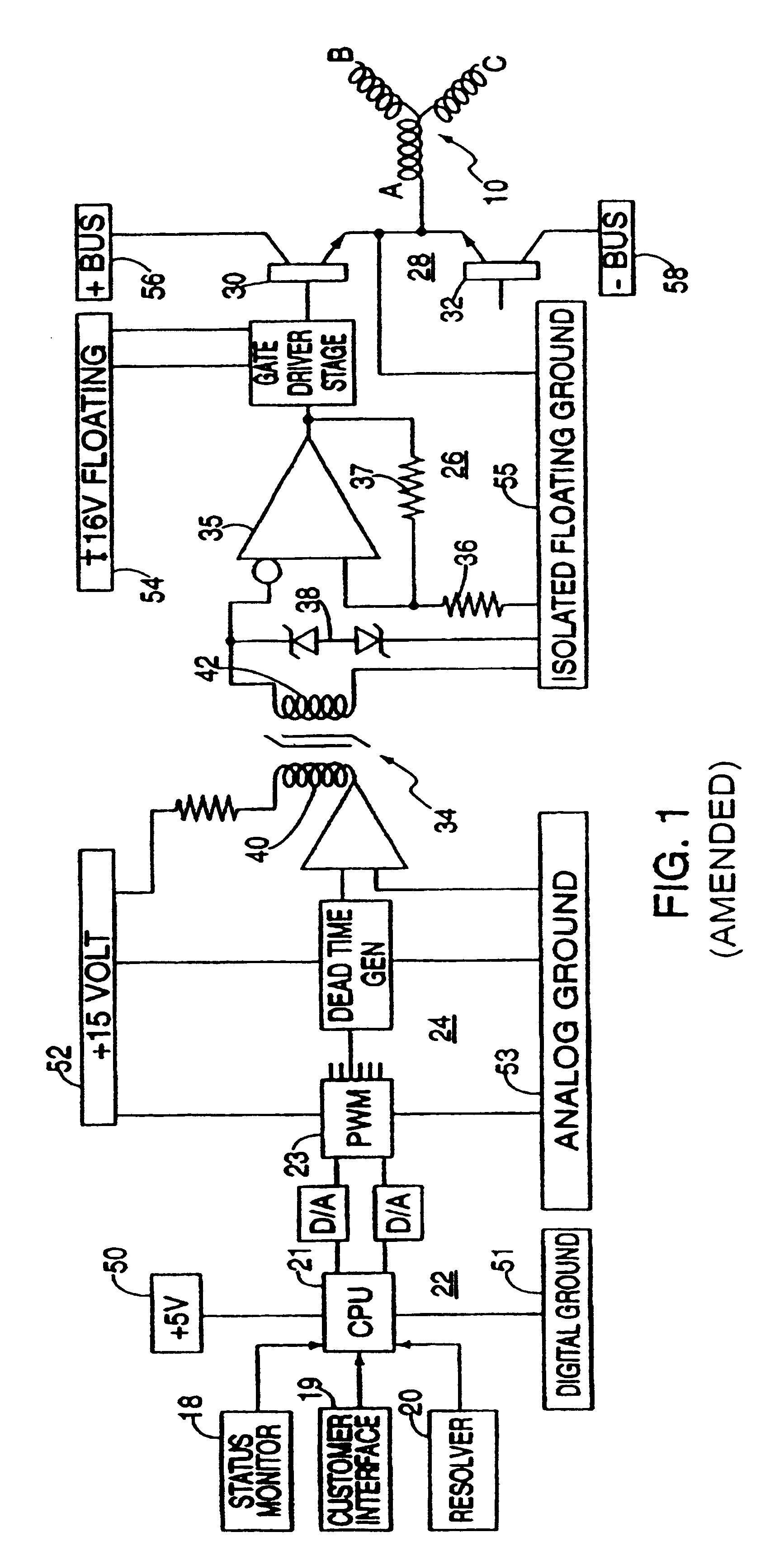
The motor controller illustrated in FIG. 1 controls a brushless motor .[.20.]. .Iadd.10 .Iaddend.having a three phase stator winding including winding phases A, B, and C. The winding phases are each displaced by 120 electrical degrees. Although the invention can be used with any type of brushless motor, it is particularly useful with motor having three phase stator windings operating in useful with motor having three phase stator windings operating in the current pulse range above 2,000 Hertz and preferably in the range of 6,000 to 20,000 Hertz or higher. Although the invention is useful with any size motor, the advantages are particularly important in controlling large and very large motors.

The motor controller includes a digital section 22 including a central processor unit (CPU), such as a microprocessor, to receive control commands and motor feedback signals to generate sinusoidal signals corresponding to the frequency, phase and amplitude of the motor excitation currents. The s...


PUM

PropertyMeasurementUnit
capacitanceaaaaaaaaaa
widthaaaaaaaaaa

Abstract

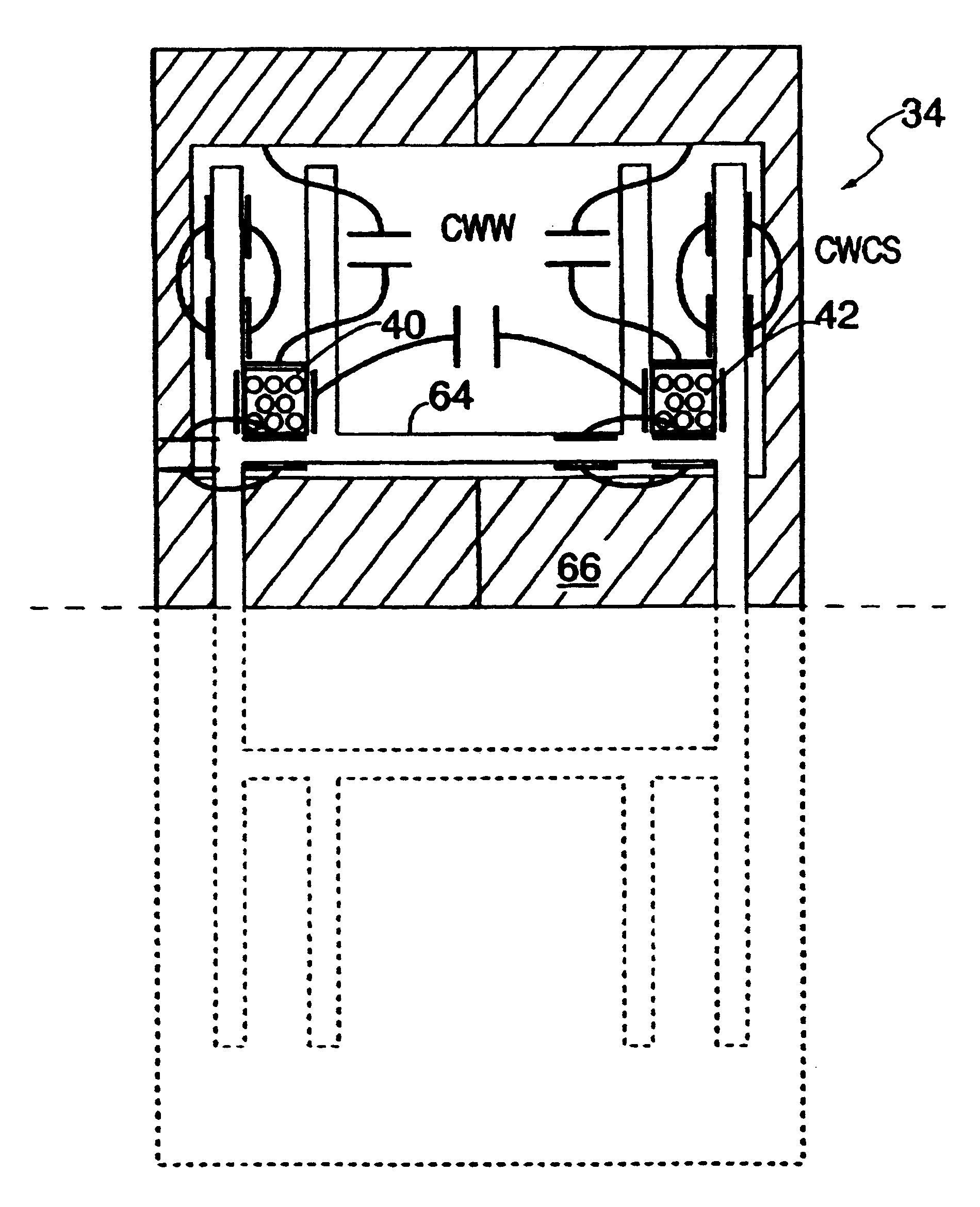
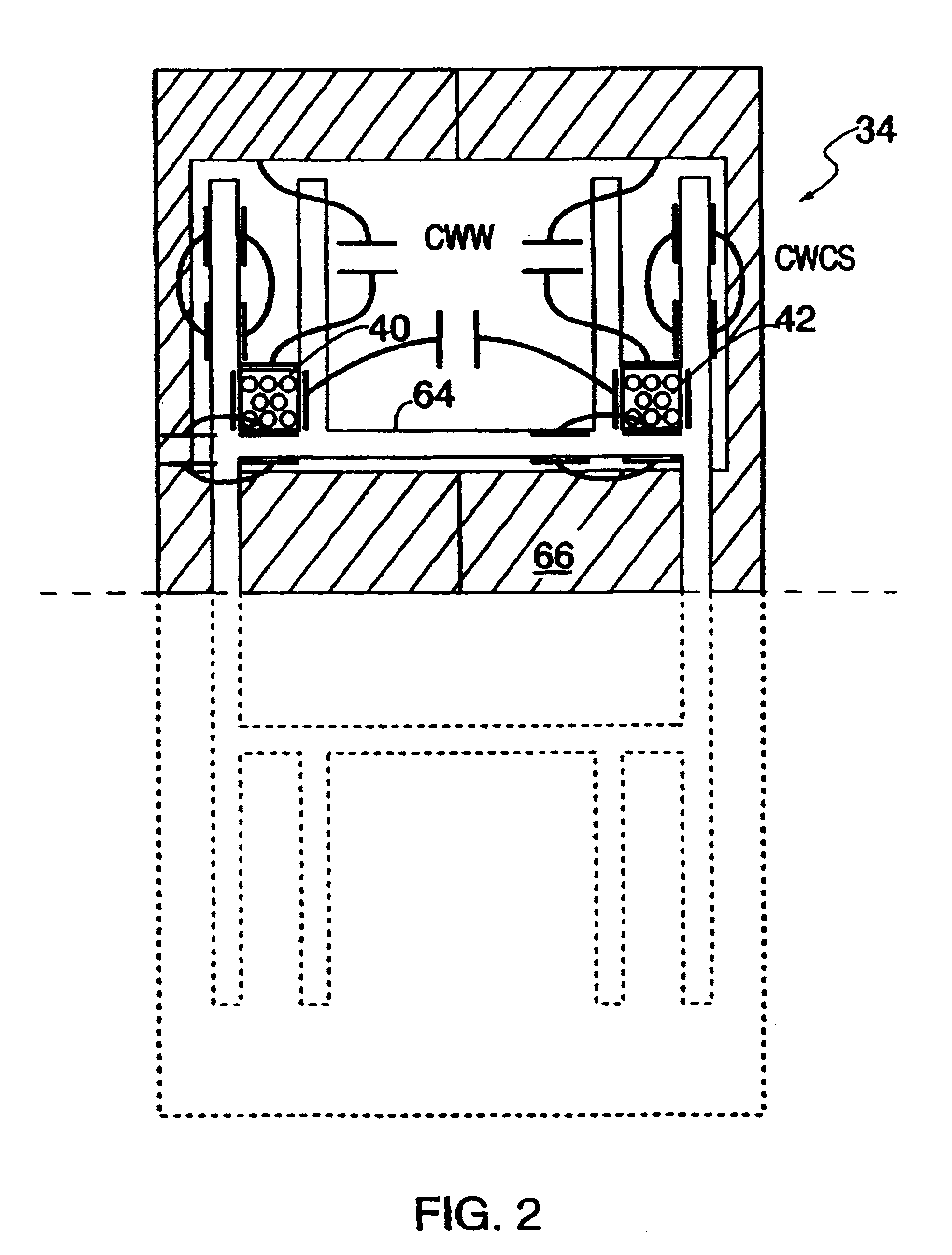
A pulse transformer for use in a high frequency motor controller to isolate the electronic control stages from the power stages in a motor controller. The primary and secondary windings are wound on a common ferrite core and spaced apart from one another. The wire size used for the windings is relatively small (gauge 37 or less). Each of the windings has between 10 and 13 turns. The interwinding capacitance must be below 5 picofarads, preferably below 1 picofarad, and most preferably below 0.2 picofarads.

Description

BACKGROUND OF THE INVENTIONU.S. Pat. No. 4,686,437 to Langley et al. entitled Electromechanical Energy Conversion System describes a motor control system whereby a microprocessor or similar electronics can be used to control electric motors. The sensitive electronics are coupled to the motor via a power transistor switching stage wherein the transistors operate in on / off fashion to control the current flow to the motor windings in accord with control signals from the microprocessor. The microprocessor receives feedback from the motor indicating rotor position and other controllable parameters. The microprocessor may also receive command signals usable for servo control. The command signals and the feedback signals are compared to determine the frequency, amplitude and phase for the winding energization, and the rotor position feedback is used to determine the proper commutation of the winding excitation. The microprocessor, either alone or with other components, provides on / off cont...

Claims


Application Information

Patent Timeline
Patent Type & Authority Patents(United States)
IPC IPC(8): H01F19/00H01F19/08H02M1/08H01F17/04H01F27/28H02M3/28H02M7/538H02M7/5387H02P6/08H02P27/06
CPCH01F17/043H01F19/08H01F2019/085H02M1/08H02M7/538H02M7/53873
Inventor VLAHU, SASO P.
Owner KOLLMORGEN CORP
Why Eureka
Try Eureka