Baseband RF voltage-current probe

a voltage-current probe and baseband technology, applied in plasma technique, electric discharge lamps, manufacturing tools, etc., can solve the problems of inability to reach inability to accurately find the phase angle, and inability to meet the output power of the rf generator. to achieve the effect of reliable and accurate, low cost and accurate detection of phase angl

Inactive Publication Date: 2003-10-14
MKS INSTR INC
View PDF5 Cites 17 Cited by
  • Summary
  • Abstract
  • Description
  • Claims
  • Application Information

AI Technical Summary

Benefits of technology

It is an objective of this invention to provide a reliable and accurate probe, at low cost, for detecting the current and voltage of RF power being applied to a plasma chamber and for accurately finding the phase angle between the applied voltage and applied current.
It is a more specific object of this invention to provide a frequency shifting arrangement that converts the voltage and current to a lower frequency baseband signal to facilitate accurate detection of RF current and voltage of the applied power, as well as phase information.

Problems solved by technology

There are non-linearities in the plasma chamber, and because of these and because of losses in the line and in the impedance matching network, not all of the output power of the RF generator reaches the plasma chamber.
Diode detectors are inherently non-linear at low signal levels, and are notoriously subject to temperature drift.
The diode detector circuits also are limited to detecting the signal peaks for the fundamental frequency only, and cannot yield any information about higher or lower frequencies present in the RF power waveform.
In addition to this, it is impossible to obtain phase angle information between the current and voltage waveforms, which renders the power measurement less accurate.
However, this proposal does have problems with accuracy and precision.
In addition, flash converters require an extremely fast RAM in order to buffer a block of samples before they are processed in a digital signal process (DSP), and fast RAM circuitry is both space-consuming and expensive.
Voltage and current probes that are now in existence are limited in their performance by the fact that they can only monitor the voltage, current, and phase angle at one frequency, and even then such probes have a poor dynamic range.
Examining a different frequency requires changing out the hardware, which can be costly and time consuming.
Unlike capacitors, inductors, and resistors, plasma chambers impose a highly non-linear load, which causes the sinusoidal waveform of the input power to become distorted.
This severely limits the accuracy of the system, and makes accurate and repeatable control impossible when there is a significant amount of voltage or current appearing in the harmonics.

Method used


Image

  • Baseband RF voltage-current probe
  • Baseband RF voltage-current probe
  • Baseband RF voltage-current probe

Examples


Embodiment Construction

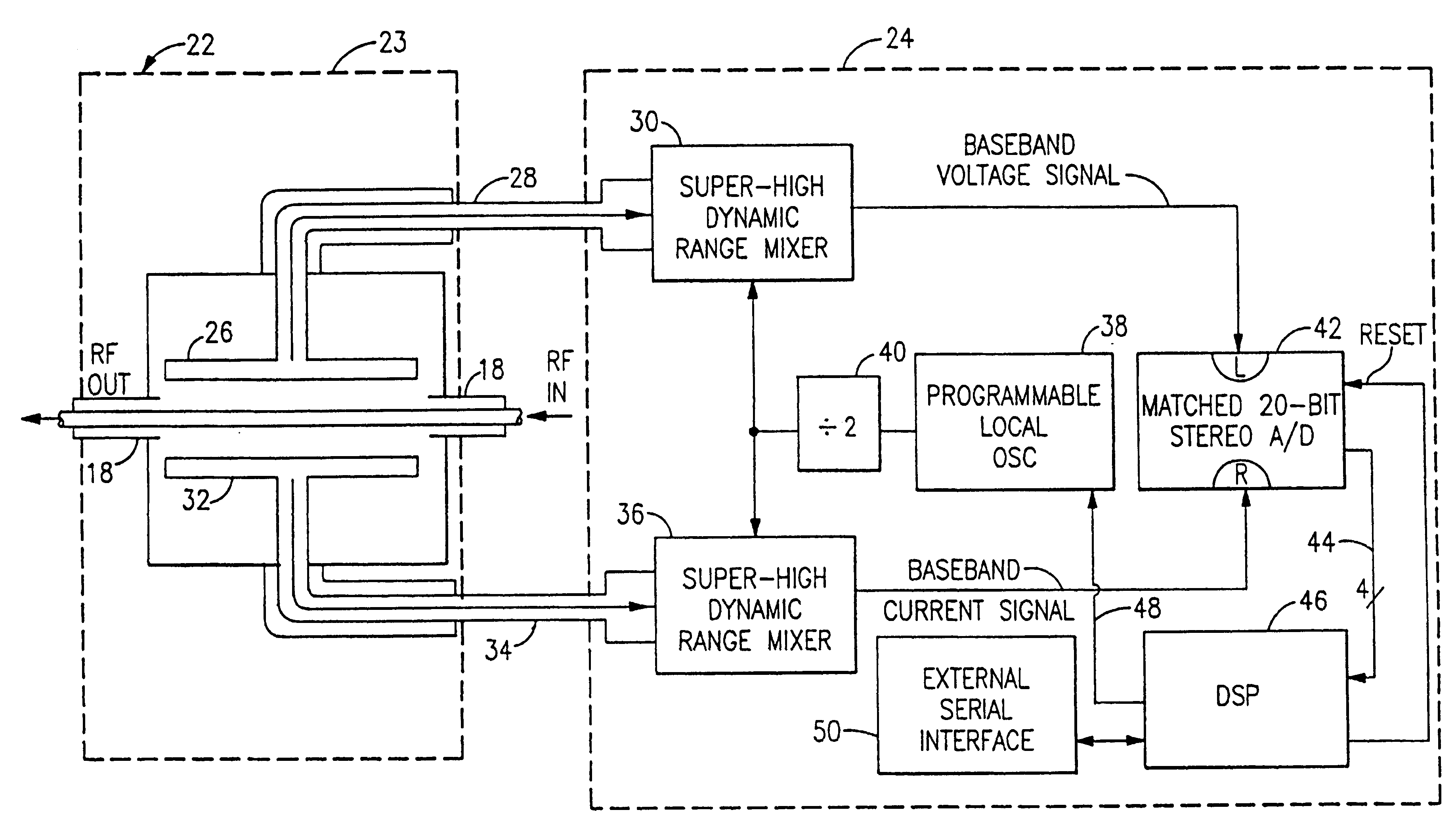
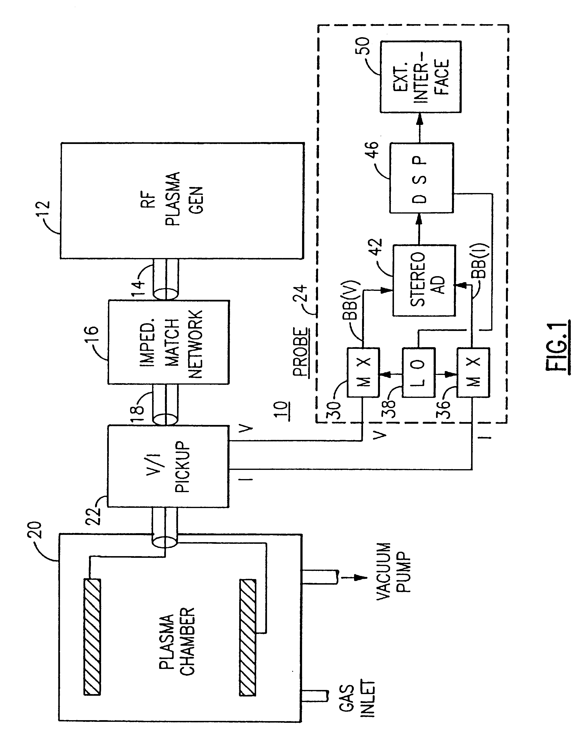
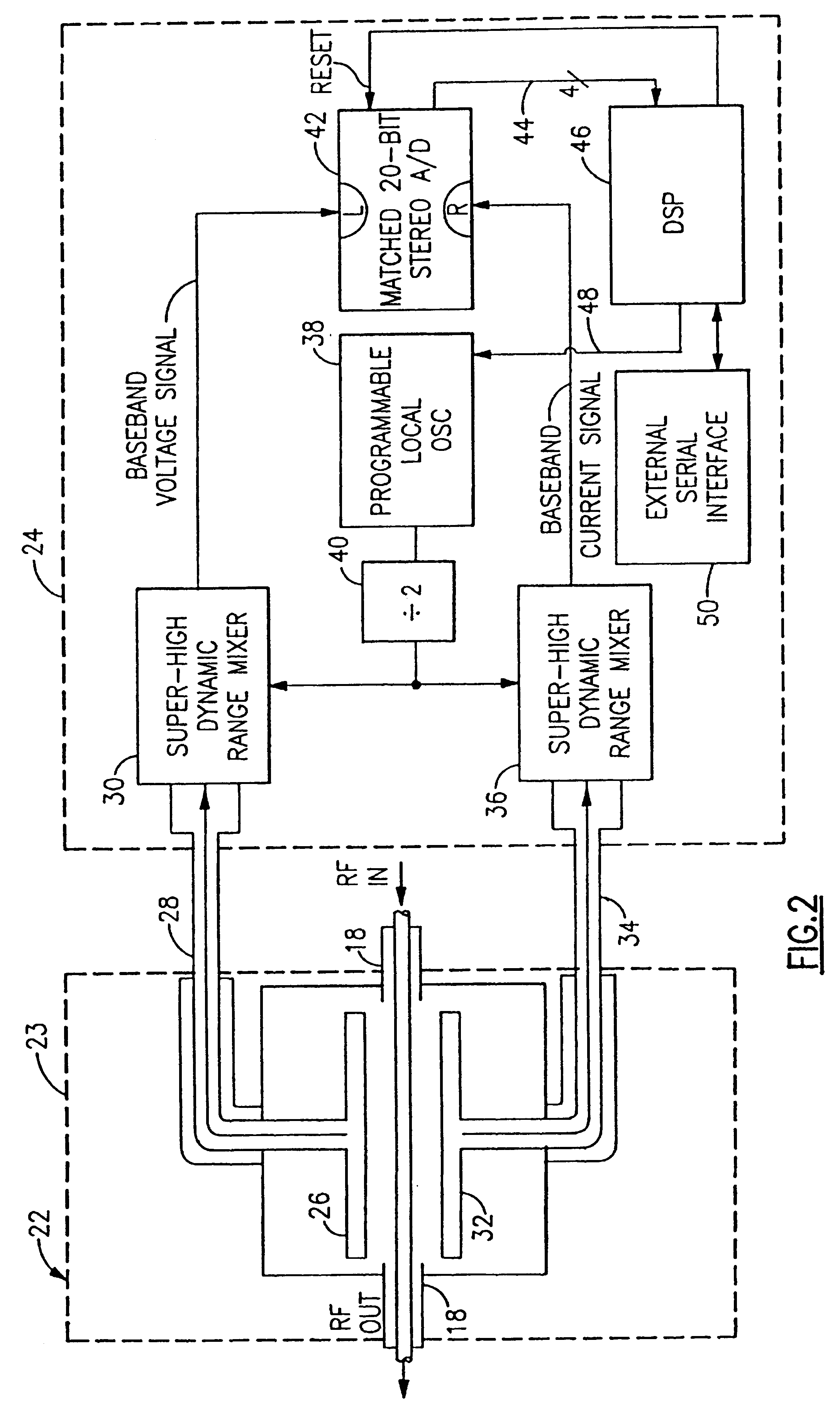
With reference to the Drawing, and initially to FIG. 1, a plasma process arrangement 10, e.g., for etching a silicon wafer or other workpiece, has an RF power generator 12, which produces RF power at a prescribed frequency, e.g., 13.56 MHz at a predetermined power level, such as one kilowatt. The generator 12 supplies RF power along a conduit 14 to a matching network 16. The output of the matching network 16 is coupled by a power conduit 18 to an input of a plasma chamber 20. A probe voltage and current pickup device 22 samples the voltage V.sub.RF and the current I.sub.RF of the applied RF power as it enters the input to the chamber 20. The chamber 20 has a vacuum conduit associated with a not-shown vacuum pump and a gas inlet through which a noble gas, e.g., argon, is introduced into the chamber. The sampled voltage and current V.sub.RF and I.sub.RF are fed to a voltage and current (V-I) baseband probe arrangement 24 which measures the magnitudes or amplitudes of the applied volta...


PUM

PropertyMeasurementUnit
frequencyaaaaaaaaaa
sampling conversion frequencyaaaaaaaaaa
frequencyaaaaaaaaaa

Abstract

An RF probe for a plasma chamber picks up current and voltage samples of the RF power applied to an RF plasma chamber, and the RF voltage and current waveforms are supplied to respective mixers. A local oscillator supplies both mixers with a local oscillator signal at the RF frequency plus or minus about 15 KHz, so that the mixers provide respective voltage and current baseband signals that are frequency shifted down to the audio range. The phase relation to the applied current and voltage is preserved in the baseband signals. These baseband signals are then applied to a stereo, two-channel A / D converter, which provides a serial digital signal to a digital signal processor or DSP. A local oscillator interface brings a feedback signal from the DSP to the local oscillator. The DSP can be suitably programmed to obtain complex Fast Fourier Transforms of the voltage and current baseband samples. The frequency-domain spectra are analyzed to obtain, with great accuracy, magnitude of voltage and current and phase angle. Other parameters are derived from these three.

Description

BACKGROUND OF THE INVENTIONThis invention relates to plasma generation equipment, and is particularly directed to probes for detecting the current, voltage, and phase of radio frequency (RF) electrical power that is being supplied to an RF plasma chamber.In a typical RF plasma generator arrangement, a high power RF source produces an RF wave at a preset frequency, i.e., 13.56 MHz, and this is furnished along a power conduit to a plasma chamber. Because there is typically a severe impedance mismatch between the RF power source and the plasma chamber, an impedance matching network is interposed between the two. There are non-linearities in the plasma chamber, and because of these and because of losses in the line and in the impedance matching network, not all of the output power of the RF generator reaches the plasma chamber. Therefore, it is conventional to employ a probe at the power input to the plasma chamber to detect the voltage and current of the RF wave as it enters the plasma...

Claims


Application Information

Patent Timeline
Patent Type & Authority Patents(United States)
IPC IPC(8): H01J37/32H05H1/00H05H1/46H01L21/205H01L21/302H01L21/3065
CPCH01J37/32082H01J37/32935H05H1/0081H01J37/32174H01J37/32183
Inventor GERRISH, KEVIN S.VONA, JR., DANIEL F.
Owner MKS INSTR INC
Why Eureka
Try Eureka