Cold cathode ion beam deposition apparatus with segregated gas flow

a technology of ion beam deposition and gas flow, which is applied in the direction of ion beam tubes, instruments, vacuum evaporation coating, etc., can solve the problems of undesirable gas flow, adverse effect on the operability and/or efficiency of the ion beam source, and adverse effect on the electric field potential between, so as to reduce the likelihood of undesired insulative material buildup

Inactive Publication Date: 2003-12-23
GUARDIAN GLASS LLC
View PDF38 Cites 61 Cited by
  • Summary
  • Abstract
  • Description
  • Claims
  • Application Information

AI Technical Summary

Benefits of technology

Another object of this invention is to provide a segregated gas flow arrangement in the context of a cold cathode ion source in order to reduce the likelihood of undesired insulative material buildups in the electrical gap between the anode and cathode.

Problems solved by technology

Unfortunately, certain of the elements in silane gas are insulative in nature (e.g., silicon carbide may be an insulator in certain applications).
This can interfere with gas flow through the gap or slit, or alternatively it can adversely affect the electric field potential between the anode and cathode proximate slit 15.
In either case, operability and / or efficiency of the ion beam source is adversely affected.
In sum, the flow of gas which produces a substantial amount of insulative material buildup in electrical gap 63 on the anode and cathode may be undesirable in certain applications.
This problem is particularly troublesome at high total flow conditions where the beam 53 can undergo a significant discontinuous transition between two operational modes (e.g., high energy / low current and low energy / high current).
Unfortunately, the sources of the '368, '593 and '447 patents primarily relate to thermionic emissive (hot) electron cathodes.
This is undesirable, as cold-cathode sources such as that of the instant invention typically operate at higher voltages and / or lower gas flows.
1 of the '208 patent where it is indicated that such sources are disadvantageous in that they are not suitable for treating large surfaces and / or have low intensity).

Method used


Image

  • Cold cathode ion beam deposition apparatus with segregated gas flow
  • Cold cathode ion beam deposition apparatus with segregated gas flow
  • Cold cathode ion beam deposition apparatus with segregated gas flow

Examples


Embodiment Construction

In the following description, for purposes of explanation and not limitation, specific details are set forth in order to provide an understanding of certain embodiments of the present invention. However, it will apparent to those skilled in the art that the present invention may be practiced in other embodiments that depart from these specific details. In other instances, detailed descriptions of well known devices, gases, fasteners, and other components / systems are omitted so as to not obscure the description of the present invention with unnecessary detail. Referring now more particularly to the accompanying drawings, in which like reference numerals indicate like parts / elements / components / areas throughout the several views.

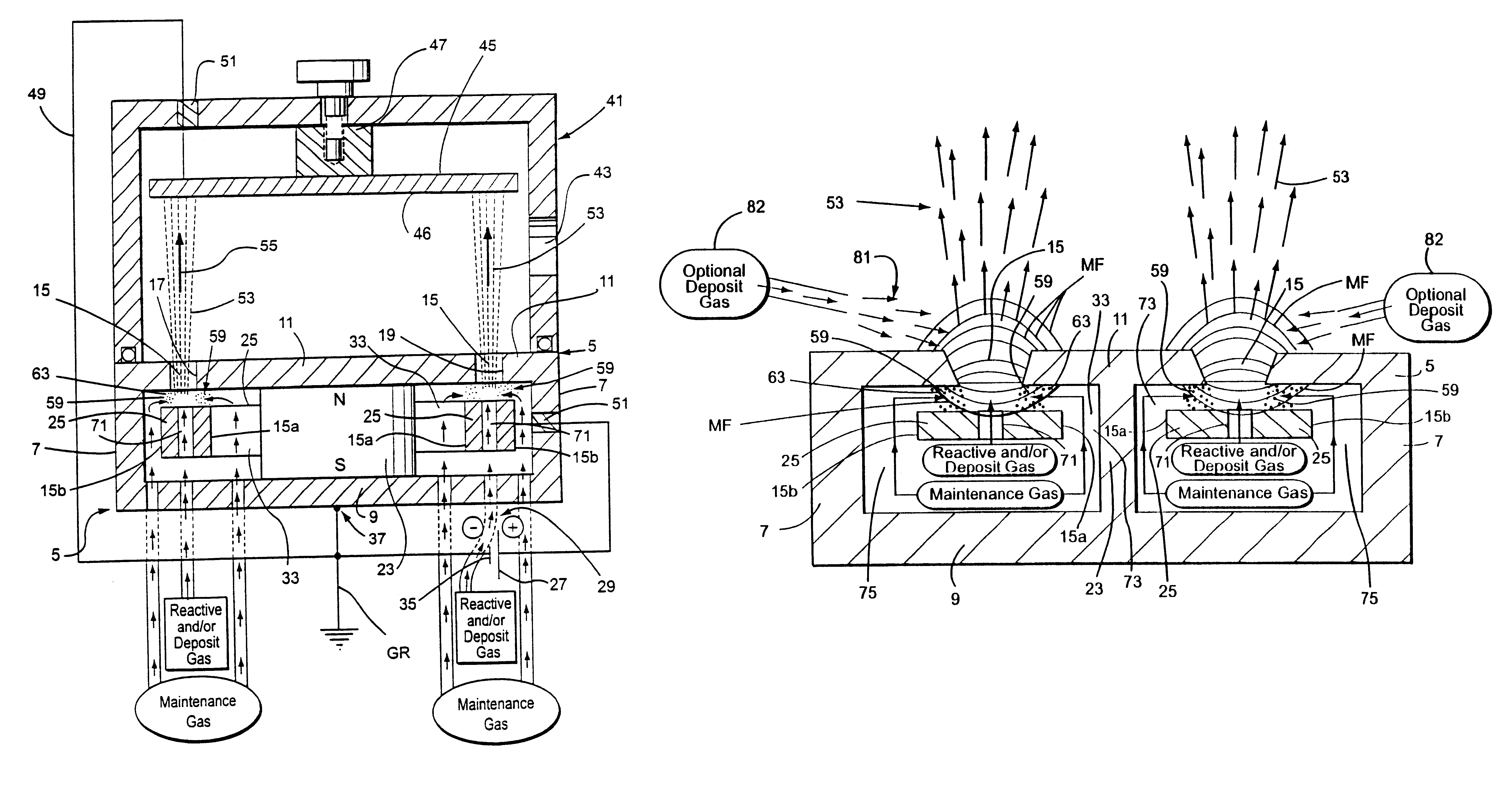
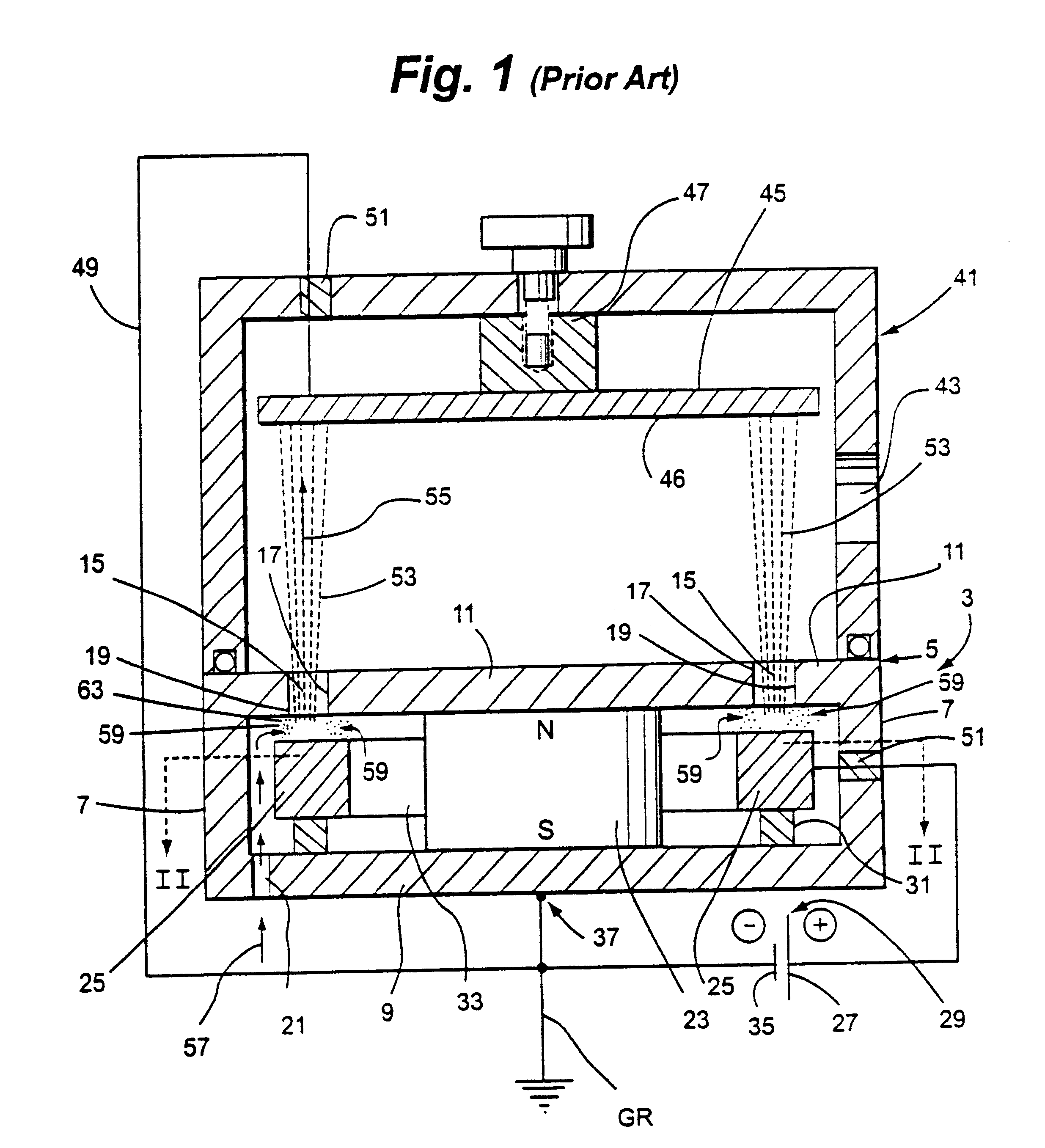
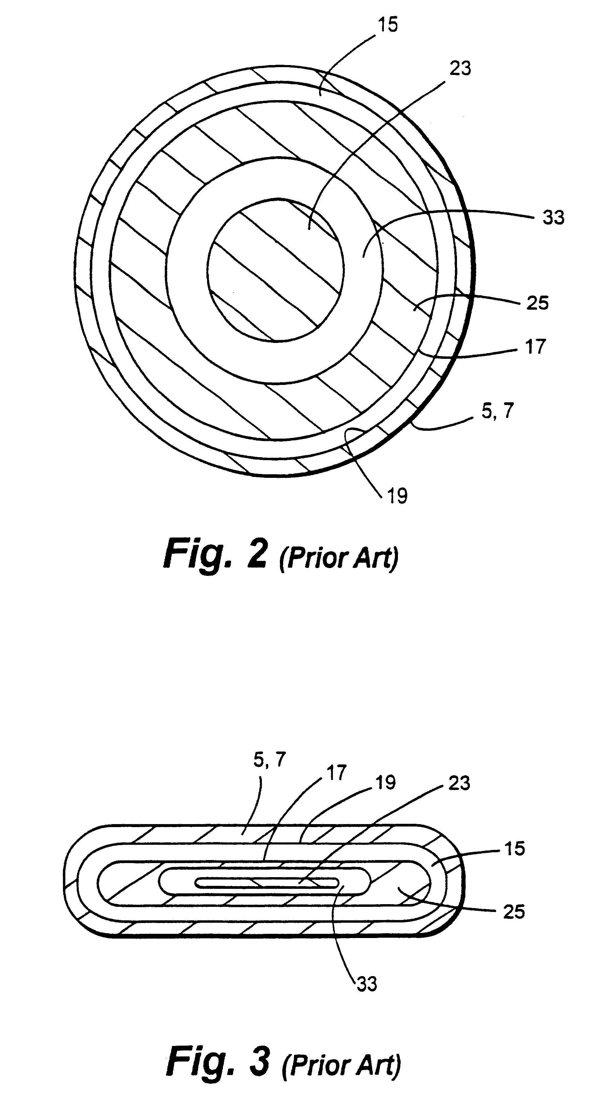
FIG. 4 is a schematic and partial sectional view of an ion source according to an exemplary embodiment of this invention. The cold cathode closed drift type ion source of FIG. 4 is similar in many respects to that of FIGS. 1-3. Closed loop ion emitting slit 15 ...


PUM

PropertyMeasurementUnit
electrical gapaaaaaaaaaa
magnetic fieldaaaaaaaaaa
areaaaaaaaaaaa

Abstract

A cold cathode closed drift ion source is provided with segregated gas flow. A first gas may be caused to flow through or along a path around a peripheral portion of an anode so as to pass through the electric gap between the anode and cathode. A second gas (different from the first gas) may be caused to flow toward the ion emitting slit, without much of the second gas having to pass through the electric gap(s). If it is desired to utilize a gas which produces insulative material (e.g., an organosilicon gas), this gas may be used as the second gas. Accordingly, insulative material buildup in the electric gap between the anode and cathode may be reduced, and changes in beam chemistry can be achieved without unduly altering ion beam characteristics.

Description

This invention relates to a cold cathode ion beam deposition apparatus with segregated gas flow, and corresponding method. More particularly, this invention relates to a cold cathode ion beam deposition apparatus wherein different gases are caused to flow through different flow channels toward an area of energetic electrons in order to provide a more efficient ion beam deposition apparatus and corresponding method.BACKGROUND OF THE INVENTIONAn ion source is a device that causes gas molecules to be ionized and then focuses, accelerates, and emits the ionized gas molecules and / or atoms in a beam toward a substrate. Such an ion beam may be used for various technical and technological purposes, including but not limited to, cleaning, activation, polishing, etching, and / or deposition of thin film coatings. Exemplary ion sources are disclosed, for example, in U.S. Pat. Nos. 6,037,717; 6,002,208; and 5,656,819, the disclosures of which are all hereby incorporated herein by reference.FIGS. ...

Claims


Application Information

Patent Timeline
Patent Type & Authority Patents(United States)
IPC IPC(8): C23C16/44C23C16/513C23C16/50H01J37/08H01J37/317C23C14/22C23C16/455H01J27/14
CPCC23C14/221C23C16/4401C23C16/45576C23C16/4558C23C16/513H01J27/143H01J37/08H01J37/3178
Inventor PETRMICHL, RUDOLPH HUGO
Owner GUARDIAN GLASS LLC
Why Eureka
Try Eureka