
Chemical mechanical planarization (CMP) slurry quality control process and particle size distribution measuring systems

a technology of mechanical planarization and quality control process, applied in the field of chemical mechanical planarization (cmp) slurry quality control process and particle size distribution measuring system, can solve the problems of difficult to check the quality of particle size distribution within these slurries, scratching or scratching the surface that is being smoothed, and thereby damage to semiconductor wafers, so as to achieve greater accuracy and measurement

Inactive Publication Date: 2007-08-21
PARTICLE MEASURING SYST
View PDF23 Cites 27 Cited by
  • Summary
  • Abstract
  • Description
  • Claims
  • Application Information

AI Technical Summary

Benefits of technology

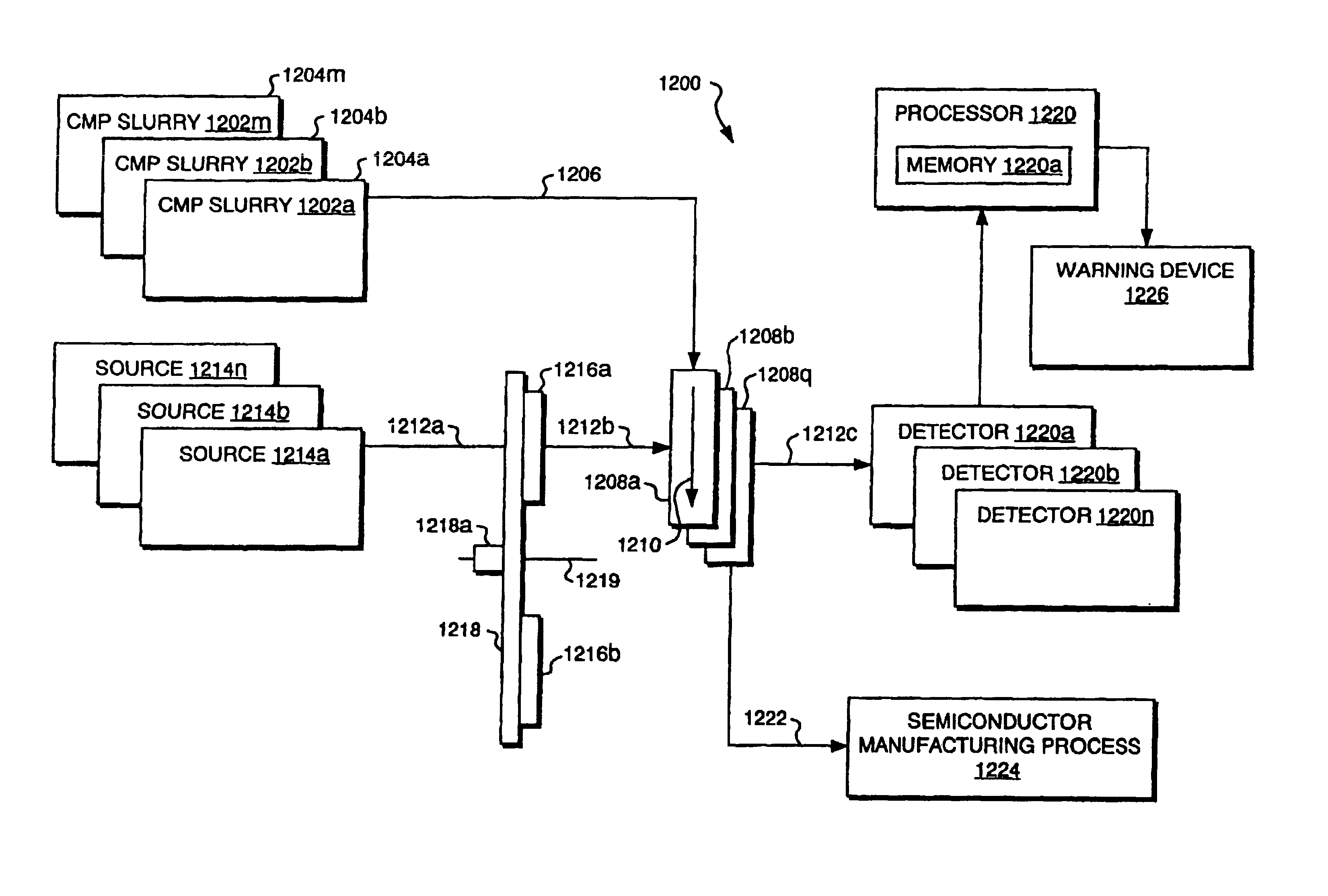
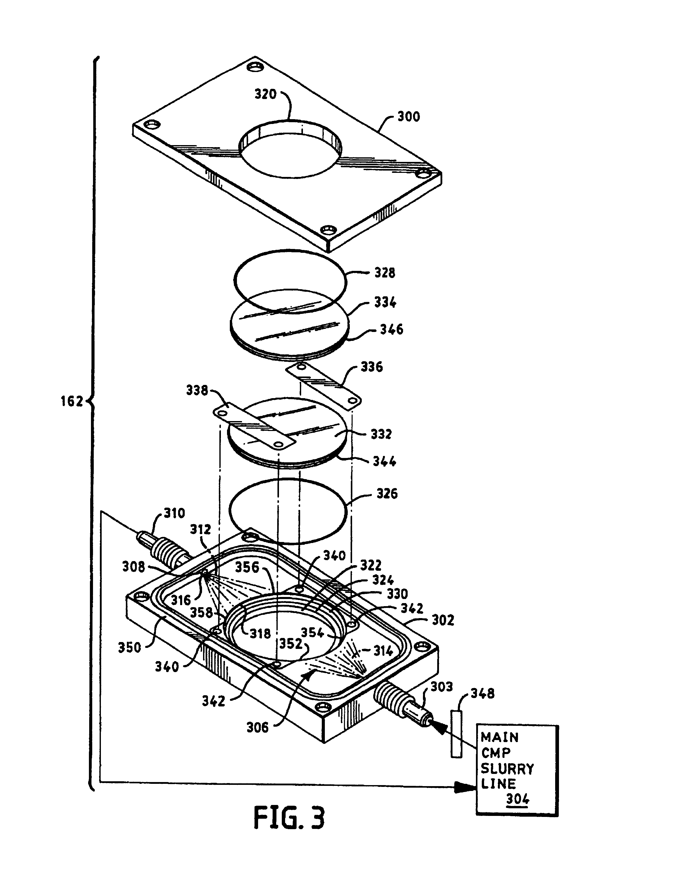
[0016]The present invention overcomes the problems outlined above, and advances the art, by providing real-time systems, methods and / or probes for continuous particle size distribution measurement and / or quality control of undiluted CMP slurry. The CMP slurry can include a broad range of particle sizes, e.g., from 0.03 μm to over 1.0 μm diameter particles. The systems and methods of the invention provide high sensitivity to small changes in physical and / or chemical characteristics of the CMP slurry (e.g., to detect changes in the particle size distribution of the CMP slurry), and preferably with autonomous operation in an industrial environment. These advantages are obtained, in certain aspects, by measuring spectral transmission through undiluted CMP slurry samples (typically through a slurry “flow”). The spectral transmission measurements are made at one or more wavelengths, and preferably at two or more wavelengths. The slurry flow typically moves through sample cells having widths as narrow as 50 microns, though typically the width is 100 microns or more. CMP slurries have high optical extinction per unit length in the visible spectrum by virtue of the high particle concentration and sub-micron particle sizes. A reasonable fraction of the incident light beam, i.e., an amount greater than approximately 5%, must penetrate the sample, without being scattered, in order to obtain useful spectral transmission data. This goal is accomplished, in one aspect, by extending the spectral transmission measurements to approximately 2.5 microns in wavelength, which is well beyond the 1.0 micron limit used in the prior art, and by utilizing specially constructed sample cells having a path length of 50-2000 microns. In another aspect, a spectral wavelength range of 0.20-2.5 microns is used to retrieve the CMP slurry particle size distribution of CMP slurries used in semiconductor manufacturing.
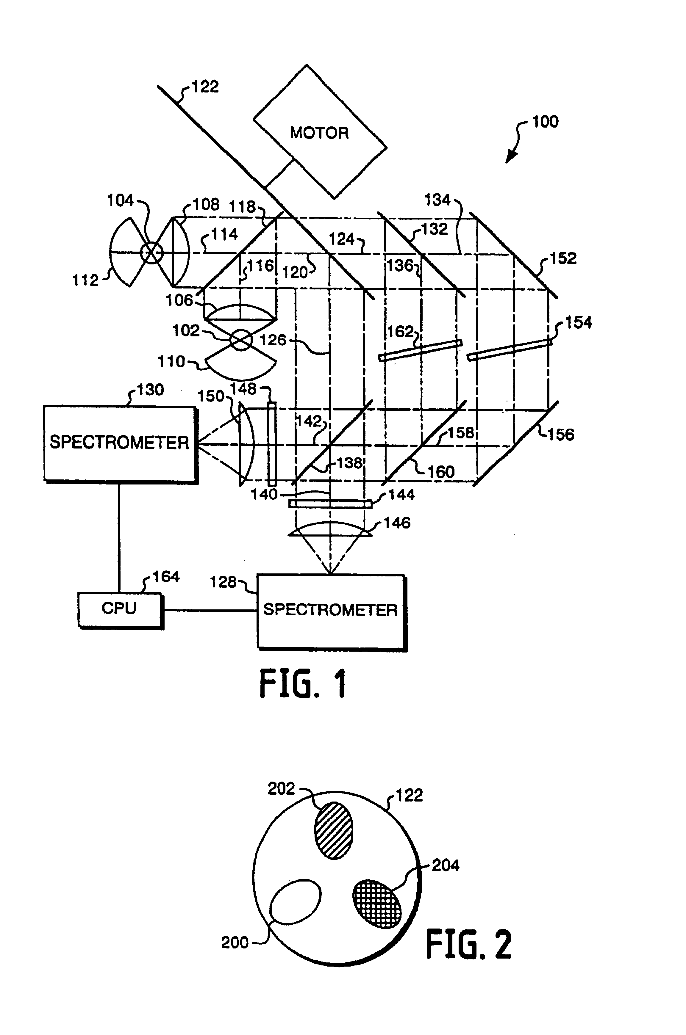
[0020]In still another aspect, a light chopper is positioned between the light source and the sample cell. The chopper contains a plurality of holes for transmitting light to the sample cell and a plurality of mirrors or solid regions for blocking transmission of light to the sample cell. The mirrors allow measurement of the time and temperature drift of the sources, while the solid regions allow measurement of the time and temperature drift of the spectrometers and their detectors. These features provide autonomous operation in an industrial environment and eliminate the need for frequent measurement of reference spectra, which would require taking the probe off-line. The computer or microprocessor preferably uses a modified Twomey / Chahine-based nonlinear iterative conversion to calculate a particle size distribution measurement from the spectral transmission measurements. A plurality of fixed grating spectrometers each having a detector array can be used to assist in this calculation. An ultrasonic disrupter can also be used to disrupt soft slurry agglomerations just prior to their entry into the sample cell.
[0039]In another aspect, the processor calculates a logarithm of transmission at each wavelength band and to determine a change in slope of logarithmic transmission versus wavelength band. This enables the system to detect changes in the particle size distribution independently from changes in particle size concentration.

Problems solved by technology

It is difficult to check the quality the particle size distributions within these slurries due to the sub-micron sizes of the particles and the substantially opaque nature of the slurry.
Particles having dimensions that exceed a delimiting value for a particular application are analogous to sandpaper having grit that is too large, and disadvantageously score or scratch the surface that is being smoothed.
It has been observed that semiconductor wafers can be scratched and thereby damaged if a significant concentration of large particles appear in the slurry through either contamination or agglomeration.
Commercially available sensor devices are presently unable to meet the needs of those who wish to measure the particle size distribution of CMP slurries.
Furthermore, dilution combined with continuous sampling creates large volumes of waste slurry.
These measurement techniques are problematic because they require (a) substantial dilution of the optically dense CMP slurries, or (b) discontinuous batch sampling of the slurry, or they have insufficient sensitivity to detect small changes in the particle size distribution over the critical size range of 0.5 to 3.0 microns.
The need to dilute CMP slurries for particle size measurements creates large amounts of waste that cannot be recovered into usable CMP slurry.
These dilution factors represent significant amounts of process slurry waste, and the dilution itself is suspected of altering the size distribution through agglomeration.
The limited wavelength range and conventional sample cell dimensions force significant sample dilution, which in turn results in generation of a large waste stream of diluted product.
An off-line batch sampling system may also be used, but this type of system has an unacceptably slow time response.

Method used


Image

  • Chemical mechanical planarization (CMP) slurry quality control process and particle size distribution measuring systems
  • Chemical mechanical planarization (CMP) slurry quality control process and particle size distribution measuring systems
  • Chemical mechanical planarization (CMP) slurry quality control process and particle size distribution measuring systems

Examples


example 2 verification

OF THE MODEL WITH EXPERIMENTAL RESULTS

[0092]FIG. 7 shows optical model predictions and experimental data for Cabot SC-1 oxide slurry, which consists of SiO2 partides immersed a pH of 10.3. This sample was diluted to 12% solids by weight, which is the concentration at which it is used for CMP wafer planarization. The particle size distribution used as input to the optical model is plotted in FIG. 8, and represents a modified version of the Cabot SC-1 PSD measured by Bare et al., Monitoring slurry stability to reduce process variability, Micro. Vol. 15, No. 8, pp. 53-63 (1997) (the BH97 particle size distribution distribution probe. A modification to the BH97 particle size distribution consisted of multiplying each particle size distribution size bin by 0.56. The 0.56 factor was chosen to obtain good fit to the measured transmission data.

[0093]FIGS. 9 and 10 show how changes in this distribution size bin factor affect the transmission spectrum, and serve as another indication of the s...


PUM


Abstract

A sensitive particle distribution probe uses special processing including a modified Twomey / Chahine iterative convergence technique and a specially constructed sample cell to obtain particle size distribution measurements from optically dense slurries, such as the slurries used in the semiconductor industry for chemical mechanical planarization. Spectral transmission data is taken over the spectral range of 0.20-2.5 microns, utilizing specially constructed, chemically resistant sample cells of 50-2000 microns thickness, and miniature, fixed grating, linear detector array spectrometers. At wavelengths greater than one micron, the preferred design utilizes InGaAs linear detector arrays. An ultrasonic disrupter can be employed to breakup harmless soft agglomerates. In addition to direct particle size distribution measurement, the invention described here could be used to detect other fundamental causes of slurry degradation, such as foaming and jelling. The probe accomplishes continuous, real time sampling of undiluted slurry. A three-position chopper allows automated operation in an industrial environment without the need for frequent reference spectra, which would require taking the probe off-line. In other embodiments, the invention provides a quality control and / or particle size measuring system for CMP slurries using transmission data through an as-used CMP slurry flow. The process of the invention detects transmission through the flow, at select wavelengths, and determines changes in the logarithmic slope of transmission versus wavelength to detect acceptable or unacceptable CMP slurries. The process can further determine CMP slurry particle size through empirical extinction data stored in memory.

Description

RELATED APPLICATIONS[0001]This application is a continuation-in-part of commonly-owned and U.S. application Ser. No. 09 / 069,682, filed on Apr. 29, 1998, <?insert-start id="INS-S-00001" date="20070821" ?>now U.S. Pat. No. 6,246,474 <?insert-end id="INS-S-00001" ?>which is incorporated herein by reference.FIELD OF THE INVENTION[0002]The invention pertains to the field of measurements performed on slurries to determine the slurry particle size distribution. More specifically, the measurements concern a use of instrumentation to determine particle concentration as a function of particle size in substantially opaque slurries, such as chemical mechanical planarization (“CMP”) slurries currently used in semiconductor manufacturing. The invention further relates to quality control processes used to improve semiconductor manufacturing processes.BACKGROUND OF THE INVENTION[0003]CMP processes are used in the semiconductor and optics industries to provide ultra-smooth surfaces. CMP...

Claims


Application Information

Patent Timeline
IPC IPC(8): G01N15/02A61B17/00A61B19/00H01L21/304
CPCA61B2017/00725G01N15/02A61B90/36A61B2090/363A61B34/10
Inventor CERNI, TODD A.WAISANEN, SCOTTKNOWLTON, DENNIS J.
Owner PARTICLE MEASURING SYST
Learn More