
An optical connector and a connection structure of optical fibers

An optical connector and connection structure technology, applied in the coupling of optical waveguides, etc., can solve the problems of reduced reliability, reduced refractive index integrating agent, pores or air bubbles on the fiber end face, etc., and achieves easy assembly and disassembly, excellent stability. Effect

Inactive Publication Date: 2009-03-04
HITACHI CABLE
View PDF10 Cites 0 Cited by
  • Summary
  • Abstract
  • Description
  • Claims
  • Application Information

AI Technical Summary

Problems solved by technology

[0008] However, in the above-mentioned conventional method, the method of polishing the end face and the sleeve of the optical fiber has a problem in that when using an optical fiber, especially an optical fiber having a plurality of periodic hollow parts (hereinafter referred to as "porous fiber") Optical fiber") When connecting optical fibers at the laying site of optical fibers, it takes a long time and takes a lot of man-hours to polish the end faces of optical fibers. Therefore, it is not suitable as a connection method for simply connecting optical fibers.
In addition, if the end face of the holey fiber is polished, the grinding dust and abrasive (used in the grinding process) generated during the grinding process will enter the cavity of the holey fiber, which may lead to an increase in connection loss and reliability. decrease in sex
[0009] On the other hand, the method of interposing a refractive index adjusting agent between the connection end faces of the optical fiber described in the above-mentioned Patent Documents 2 and 3 generally uses a silicon-based or paraffin-based liquid or fatty refractive index adjusting agent, and therefore, in use When optical connectors having these refractive index matching agents inside are used to connect optical fibers, there is a problem that the refractive index matching agent enters the cavity of the holey fiber
In general, the refractive index of the refractive index matching agent has temperature dependence, and therefore, there is a problem that the transmission loss of the holey fiber significantly changes as the refractive index of the refractive index matching agent entering the cavity portion of the holey fiber changes.
In addition, since the index-adjusting agent enters the cavity portion of the holey fiber, there is a problem that the index-adjusting agent between the end faces of the fiber is reduced, and voids or air bubbles tend to be generated between the end faces of the fiber, so that the optical properties of the holey fiber are significantly improved. reduce
[0010] In addition, although there is also a method of sealing the cavity portion of the end face of the holey fiber before the fiber is connected, a special device is required for such sealing at the laying site of the fiber; It takes a long time, so the cost of connecting optical fibers is increased, and it is not suitable as a connection method for simply connecting optical fibers
[0011] In addition, in the methods of using thin films described in the above-mentioned Patent Documents 4, 5, and 6, since the diameter of the optical fiber is very thin such as 80 μm or 125 μm, it is very difficult to attach the thin film to the end surface of the optical fiber with high precision. Attached to the fiber end, the film still needs to be cohesive or adhesive
Therefore, when performing optical fiber connection work at the optical fiber laying site, there is a problem that foreign matter such as dust tends to adhere to the film, resulting in a decrease in the reliability of the optical fiber or a reduction in the work efficiency of the optical fiber connection operation.

Method used


Image

  • An optical connector and a connection structure of optical fibers
  • An optical connector and a connection structure of optical fibers
  • An optical connector and a connection structure of optical fibers

Examples


Embodiment 1

[0062] Next, a first embodiment of the present invention will be described.

[0063] As a cross-linking and curing type refractive index adjusting agent, 1.0 parts by weight of a cross-linking agent (manufactured by Nippon Polyurethane Industry Co., Ltd., trade name: Coronet L) was added to a mixture of n-butyl acrylate / methyl acrylate / acrylic acid / methyl acrylate. A solution obtained by mixing 50% ethyl acetate solution of an acrylic resin composed of 2-hydroxyethyl acrylate copolymer (composition ratio: 82 / 15 / 2.7 / 0.3 (parts by weight)).

[0064] For the crosslinked curable refractive index conformer after crosslinking and curing the acrylic adhesive material coating liquid (crosslinkable curable refractive index conformer) obtained as described above, measure the 1300-1600nm wavelength range with a spectrophotometer The result of light transmittance is 93-95%. In addition, as a result of measuring the refractive index of the cross-linked curable refractive index-modified bo...

Embodiment 2

[0074] Next, a second embodiment of the present invention will be described.

[0075] As a cross-linking curing type refractive index adjusting agent, an addition-type silicon-based adhesive material coating solution consisting of SD4590 / BY24-741 / SX212 / toluene (composition ratio: 100 / 1.0 / 0.9 / 50 (parts by weight)) was prepared (SD4590, BY24-741, and SRX212 are all manufactured by Toray Douko-Ninge Co., Ltd.).

[0076] Use a spectrophotometer to measure the wavelength range of 1300-1600nm of the crosslinked curable refractive index conformer after crosslinking and curing the addition type silicon-based adhesive material coating solution (crosslinked curable refractive index conformer) obtained above. The result of light transmittance is 92-94%. On the other hand, the result of measuring the refractive index of the cross-linked curable refractive index integrated body with an Abbe refractometer is within 1.465±0.005 at normal temperature (23±2° C.).

[0077] In addition, the el...

Embodiment 3

[0098] Next, a third embodiment of the present invention will be described.

[0099] As a cross-linking and curing type refractive index adjusting agent, 1.0 parts by weight of a cross-linking agent (manufactured by Nippon Polyurethane Industry Co., Ltd., trade name: Coronet L) was added to a mixture of n-butyl acrylate / methyl acrylate / acrylic acid / methyl acrylate. A solution obtained by mixing 50% ethyl acetate solution of an acrylic resin composed of 2-hydroxyethyl acrylate copolymer (composition ratio: 82 / 15 / 2.7 / 0.3 (parts by weight)).

[0100] For the crosslinked curable refractive index conformer after crosslinking and curing the acrylic adhesive material coating liquid (crosslinkable curable refractive index conformer) obtained as described above, measure the 1300-1600nm wavelength range with a spectrophotometer The result of light transmittance is 93-95%. In addition, as a result of measuring the refractive index of the cross-linked curable refractive index-modified bo...


PUM


Abstract

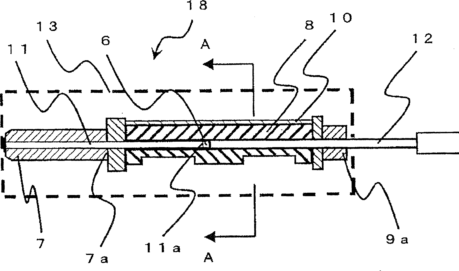
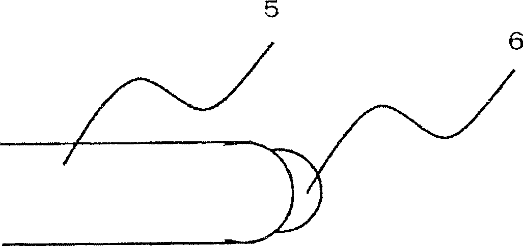
The invention relates to an optical connector and a connection structure of optical fibers. To connect optical fibers to each other in the state of being cut without polishing end faces of the optical fibers after cutting them. The optical connector is provided with a ferrule 7 with a 1st built-in optical fiber 11, and an optical fiber connector 9 connected with an end edge of the ferrule 7, and the end face of a 2nd optical fiber 12 inserted from the end edge side 9a of the optical fiber connector 9 and the end edge side end face 11a of the 1st optical fiber 11 are butt-connected. A cross-linking-hardening refractive index matching body 6 is adhering to the end edge side end face 11a, and the cross-linking-hardening refractive index matching body 6 cross-linking-hardens a cross-linking-hardening refractive index matching agent applied to the end edge side end face 11a of the optical fiber 11.

Description

technical field [0001] The present invention relates to an optical connector, and more particularly to an optical connector capable of easily performing optical fiber connection work at the laying site of the optical fiber. In addition, the present invention also relates to an optical fiber connection structure. Background technique [0002] At present, as a method of connecting optical fibers, a method of physically connecting optical fibers in close contact with each other or ferrules containing optical fibers in close contact with each other is generally widely used. For example, examples of such a physical connection method include a connection method using mechanical splicing, a connection method using an optical connector, and the like. Also, in general, when performing permanent connection (connection in which attachment and detachment are basically not performed after the optical fibers are connected), a connection method using mechanical splicing is suitable. In a...

Claims


Application Information

Patent Timeline
Patent Type & Authority Patents(China)
IPC IPC(8): G02B6/38G02B6/36
Inventor 加藤善久铃木香菜子椎名则文西尾友幸大薗和正滑川嘉一中谷佳广
Owner HITACHI CABLE
Learn More