Inverted pendulum of remote car with two wheels and balance control method thereof
A technology of inverted pendulum and trolley, which is applied in vehicle position/route/height control, attitude control, adaptive control, etc., and can solve the problems of algorithm failure, equipment damage, limited movement on horizontal guide rails or horizontal platforms, or fixed problems such as movement within the point range, to achieve the effect of increasing the difficulty of control
- Summary
- Abstract
- Description
- Claims
- Application Information
AI Technical Summary
Problems solved by technology
Method used
Image
Examples
Embodiment 1
[0060] Embodiment 1: Inverted pendulum of two-wheeled remote control trolley and its control method
[0061] 1. The hardware of the inverted pendulum of the two-wheeled remote control car:
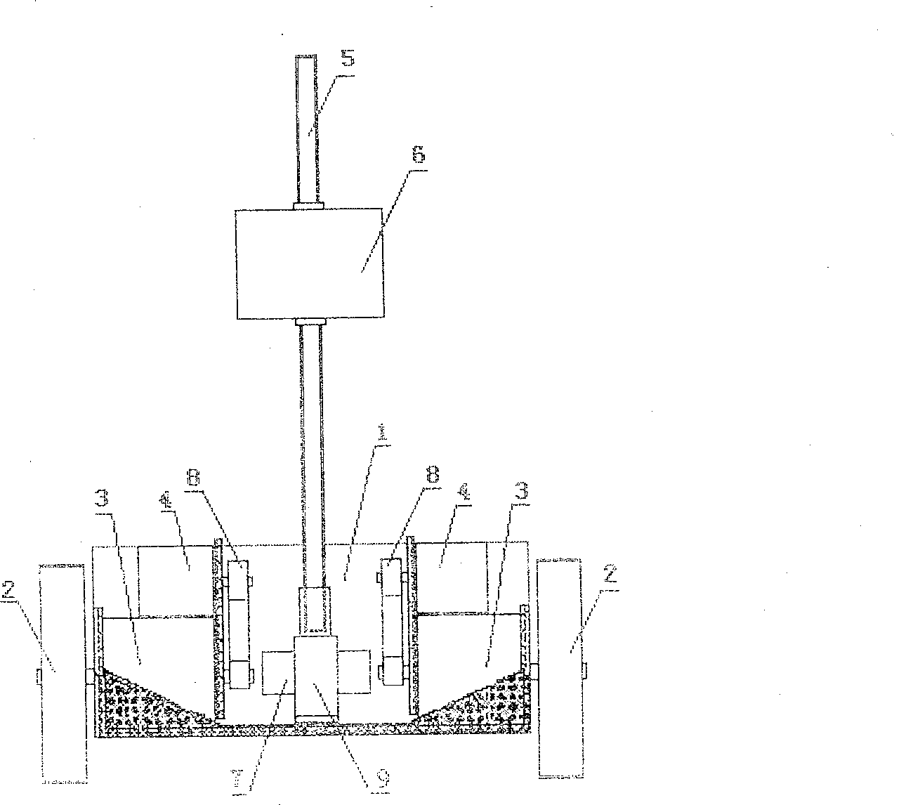
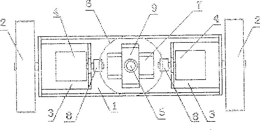
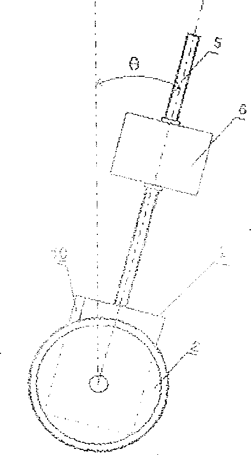
[0062] The chassis (230x80mm) of the body (1) (length x width x height 230 x 80 x 90mm) of the present embodiment two-wheeled remote control dolly inverted pendulum and "several" type support (9) (length x width x height 64 x 30 x 90mm) 60mm) is made of stainless steel plate (thickness 2mm) to ensure strength, wheels (2) (φ120mm), swing rod (5) (φ10*500mm) and other mechanical parts are made of aluminum alloy plate (thickness 2mm~3mm) to reduce The car weighs itself. The installation of components should be evenly distributed as far as possible, so that the weight of the device is symmetrical, especially the weight of the car body perpendicular to the axle should be symmetrical.
[0063] 1. Selection of each functional module:
[0064]The controller (11) in the present embodiment adopts...
Embodiment 2
[0178] Example 2: Two-wheeled remote control trolley two-stage inverted pendulum and multi-stage inverted pendulum
[0179] Based on the embodiment of the inverted pendulum of the above-mentioned two-wheeled remote control trolley of the present invention, it can also be made into an inverted pendulum of two, three or more levels, as follows:
[0180] One of the manufacturing methods of the two-stage inverted pendulum, as shown in Figure 16: the car body (1) and the swing rod (5) rotate around the wheel (2) axis; Another fork (16), the fork (16) can rotate around the hinge point, and their rotation surfaces are all perpendicular to the axis of rotation; an additional angle measuring device is installed at the position coaxial with the axis of rotation at the hinge , so that it can measure the angle (θ1-θ2) formed between the two pendulums; in this way, the car body (1) and the original pendulum (5) affixed to it constitute the first level pendulum (bottom), and the first level...
Embodiment 3
[0184] Example 3: A two-wheeled remote control trolley capable of avoiding obstacles Two-stage inverted pendulum
[0185] Based on the embodiment 1 of the inverted pendulum of the above-mentioned two-wheeled remote control trolley of the present invention, the inverted pendulum can also be made to have the function of avoiding obstacles ahead, and the method is as follows:
[0186] The ultrasonic ranging module includes a transmitter (17) and two receivers (18). The ultrasonic module is similar to the remote control module and consists of two parts: transmitting and receiving. The transmitting part is composed of a 38KHZ frequency generator and an ultrasonic transmitting probe; the receiving part is composed of a receiving probe and a sensor amplifier circuit. Their power supply voltage is 5V; the 38KHZ frequency generator is implemented by the internal program of the DSP controller, and directly drives the transmitting probe through the IOPF6 port of the DSP controller; the t...
PUM
 Abstract
Description
Claims
Application Information
 - R&D
- Intellectual Property
- Life Sciences
- Materials
- Tech Scout
- Unparalleled Data Quality
- Higher Quality Content
- 60% Fewer Hallucinations
Browse by: Latest US Patents, China's latest patents, Technical Efficacy Thesaurus, Application Domain, Technology Topic, Popular Technical Reports.
© 2025 PatSnap. All rights reserved.Legal|Privacy policy|Modern Slavery Act Transparency Statement|Sitemap|About US| Contact US: help@patsnap.com


