Sealed rechargeable battery and manufacturing method of the same

A secondary battery, airtight technology, used in secondary battery manufacturing, secondary batteries, battery pack components, etc., can solve the problems of inability to interrupt the current path, battery temperature rise, battery internal resistance increase, etc.

Active Publication Date: 2009-07-08
PANASONIC CORP
View PDF8 Cites 0 Cited by
  • Summary
  • Abstract
  • Description
  • Claims
  • Application Information

AI Technical Summary

Problems solved by technology

[0005] However, the problem to be solved for the sealing plate of the lithium ion secondary battery used in consumer equipment is that as the inner liner for sealing by caulking the metal filter, a molded liner made of synthetic resin such as polypropylene is usually used. Under the action of factors such as drop, vibration, and high temperature storage, the resin inner liner will cause a decrease in elastic force over time, which will lead to a decrease in caulking force, thereby reducing the contact resistance of internal parts. increase
[0006] In addition, the problem with the structure of JP-A-2000-90892 is that since the metal thin-walled valve body is not installed, the excessive current path cannot be blocked when the battery is mistakenly overcharged, etc., so the electrolytic The rapid decomposition of liquid and electrode active material is further promoted, causing the temperature of the battery to rise, which develops into a situation where gas is emitted
[0007] Furthermore, the problem with the structure of JP-A-2001-126695 is that although a part of the safety valve member and the metal cap are welded together, most of the sealing plate is mechanically joined together by caulking. Therefore, under the action of factors such as drop, vibration, and high-temperature storage, the caulking force will decrease with time, which will increase the contact resistance of internal parts, which will lead to an increase in the internal resistance of the battery.

Method used


Image

  • Sealed rechargeable battery and manufacturing method of the same
  • Sealed rechargeable battery and manufacturing method of the same
  • Sealed rechargeable battery and manufacturing method of the same

Examples


Embodiment approach

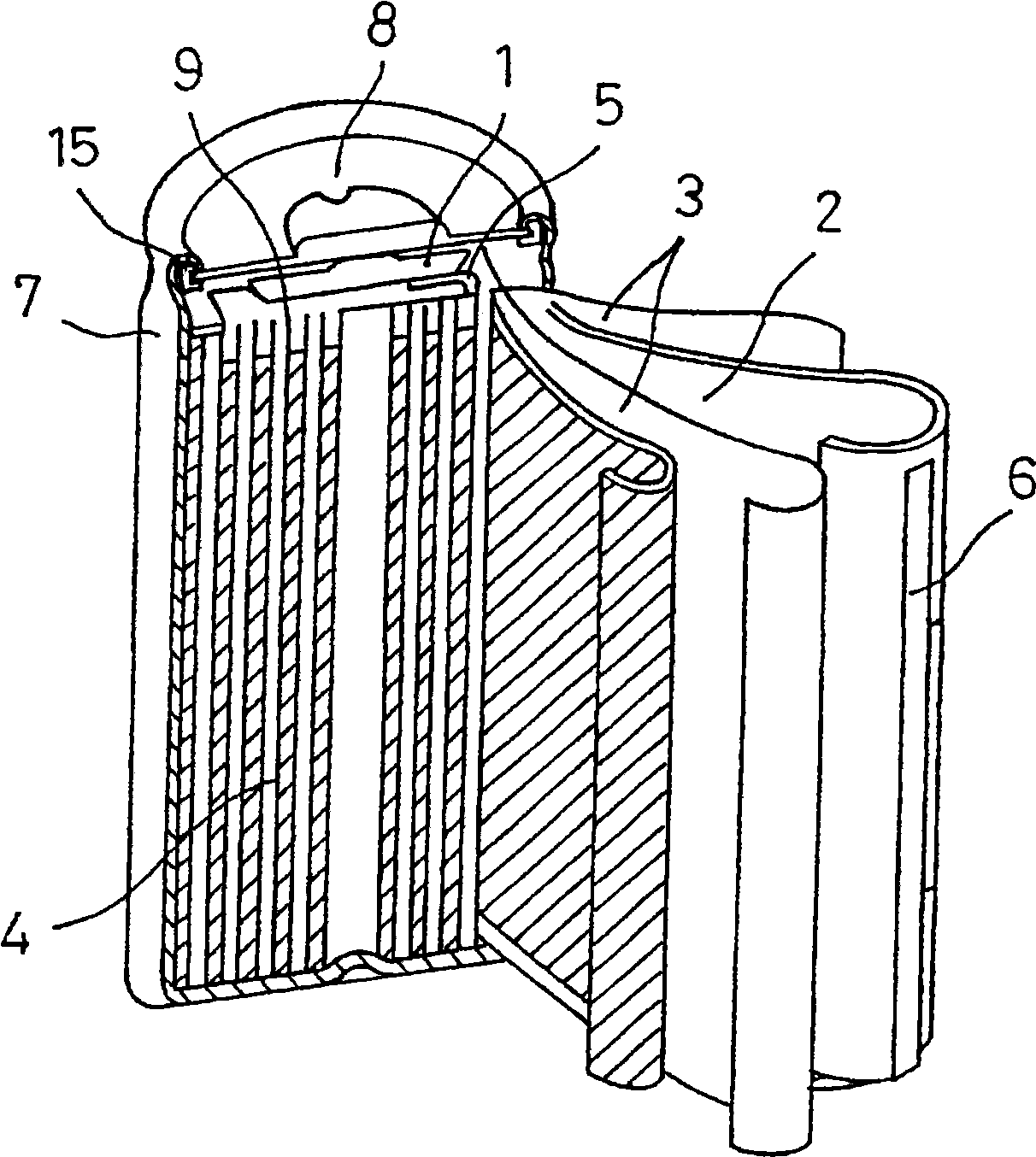
[0024] Next, with regard to the sealed secondary battery according to the embodiment of the present invention, while referring to the attachment of the cylindrical lithium ion battery with the most remarkable effect, Figure 1 side to explain.

[0025] figure 1 is a schematic longitudinal sectional view of a cylindrical lithium ion battery according to an embodiment of the present invention. exist figure 1 Among them, the cylindrical lithium-ion battery has a cylindrical plate group 4 wound into a spiral shape, wherein the plate group 4 is configured with: a positive electrode plate 1 coated with a positive electrode mixture on an aluminum foil current collector; A negative electrode plate 2 coated with a negative electrode mixture on a foil current collector; and a diaphragm 3 with a thickness of 25 μm between the two electrodes. The positive electrode lead current collector 5 was welded to the aluminum foil current collector by laser welding. The negative electrode lead ...

Embodiment 1

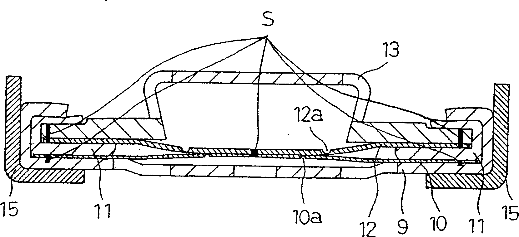
[0036] figure 2 It is a configuration diagram of the sealing plate of the sealed secondary battery of the present invention. exist figure 2 Among them, the sealing plate 8 is manufactured as follows. First, aluminum is press-worked to produce a disk-shaped metal filter 9 having a plurality of openings. Next, aluminum with a thickness of 0.15 mm was punched into a disc shape, and a circular thin-walled portion 10 a was formed in the center by marking, thereby producing the metal thin-walled valve body 10 . Next, polybutylene terephthalate (PBT) resin is injection-molded to produce a resin-made inner liner 11 of a predetermined size. Next, after punching out aluminum with a thickness of 0.15 mm into a disk shape, a C-shaped thin wall portion 12 a was formed at the center to manufacture a metal explosion-proof valve body 12 . The metal cap 13 is produced by press-working iron and then plating it with a nickel plating layer of about 3 μm. The components of the sealing plate...

Embodiment 2

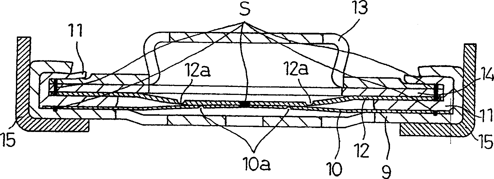
[0042] image 3 It is a configuration diagram of another sealing plate 8 of the sealed secondary battery of the present invention. For the battery made in the same way as in Example 1, its sealing plate 8 is as image 3 As shown, after press working stainless steel, a 3 μm nickel plating layer was plated to produce a disk-shaped metal spacer 14 . On the periphery of the metal cap 13 and the metal spacer 14 , eight welded portions S are formed by resistance welding at equal intervals. On the peripheral part of the member to be joined and the metal explosion-proof valve body 12, eight welded parts S are formed at equal intervals by laser. The members joined in this way are inserted above the resin inner liner 11 to be in contact with the metal explosion-proof valve body 12, except that the sealing plate 8 obtained in the same manner as the sealing plate of Example 1 is used to obtain the embodiment. 2 sealed secondary batteries.


PUM

PropertyMeasurementUnit
impedanceaaaaaaaaaa
impedanceaaaaaaaaaa
impedanceaaaaaaaaaa

Abstract

The present invention relates to a sealed secondary battery, wherein an electrode group and an electrolyte are accommodated in a battery container composed of a metal bottom case and a sealing plate, wherein the electrode group is composed of a positive electrode material attached to a positive electrode current collector. The positive electrode plate and the negative electrode plate in which the negative electrode material is attached to the negative electrode current collector are wound by being separated by a diaphragm. The sealing plate is composed of a metal filter that constitutes an internal terminal, a safety mechanism that blocks the current path and discharges gas to the outside when the battery internal pressure is abnormal due to overcharging, etc., and a resin lining is stacked and accommodated The gasket and the metal cap terminal constituting the external terminal are sealed by caulking and sealing the peripheral portion of the metal filter so as to sandwich the resin inner gasket. Since the metal filter mesh and all the metal members housed in the metal filter mesh are joined by welding, it is possible to obtain a sealed secondary battery which has a sealing plate with a small impedance and requires high output power and large current discharge. .

Description

technical field [0001] The present invention relates to a sealed secondary battery suitable for a driving power supply, and more particularly to a sealed secondary battery having a low impedance and a sealing plate structure suitable for large current discharge, and a method for manufacturing the same. Background technique [0002] Among sealed secondary batteries, lithium-ion secondary batteries are used in a variety of applications due to their light weight, small size, and high energy density, ranging from consumer equipment represented by mobile phones to electric vehicles and electric Power supply for driving tools, etc. Especially in recent years, it has attracted much attention as a power supply for driving, and research towards high energy density and high output power is in the ascendant. The sealing plate of the lithium-ion secondary battery used in the current civilian equipment generally has the structure shown in FIG. 4 . Inside the metal filter 19 constitutin...

Claims


Application Information

Patent Timeline
Patent Type & Authority Patents(China)
IPC IPC(8): H01M2/04H01M2/08H01M2/12H01M2/00H01M10/04H01M10/40H01M10/0587H01M50/152H01M50/169
CPCY02E60/122Y02E60/10Y02P70/50
Inventor 神月清美桥本达也井上广树平川靖
Owner PANASONIC CORP
Why Eureka
Try Eureka