
Aeration type convection mixing ink-removing flotation tank

An aeration type, flotation cell technology, applied in the field of pulping and papermaking equipment, can solve the problem that small and medium-sized waste paper deinking pulp mills are difficult to promote in a large area, the amount of bubble generation and distribution range is difficult to adjust, and the mixing of pulp and gas Unable to adjust the uniformity and other problems, to achieve the effect of small footprint, stable bubbles and simple processing

Inactive Publication Date: 2009-09-02
SOUTH CHINA UNIV OF TECH
View PDF4 Cites 0 Cited by
  • Summary
  • Abstract
  • Description
  • Claims
  • Application Information

AI Technical Summary

Problems solved by technology

[0003] (1) The mixing uniformity of the slurry and gas cannot be adjusted for the aeration element using a stepped diffuser, so there is a phenomenon of uneven flotation
[0004] (2) Since the stepped diffuser can generate relative negative pressure only at a certain flow rate, the diameter of the slurry inlet pipe is often relatively small, which increases the resistance loss of the entire system and easily causes the slurry to block the pipeline. Phenomenon
[0005] (3) The flotation cell using a special bubble generator, because the structure of the bubble generator is complex, the amount of bubble generation and the distribution range are not easy to adjust, so it is difficult to carry out large-scale promotion for general small and medium-sized waste paper deinking pulp mills

Method used


Image

  • Aeration type convection mixing ink-removing flotation tank
  • Aeration type convection mixing ink-removing flotation tank
  • Aeration type convection mixing ink-removing flotation tank

Examples


Embodiment Construction

[0028] The present invention will be described in further detail below in conjunction with the accompanying drawings, but the embodiments of the present invention are not limited thereto.

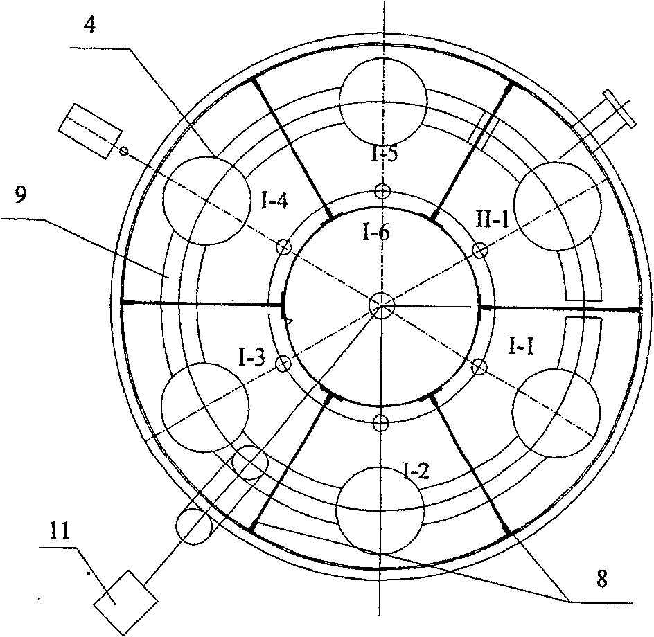
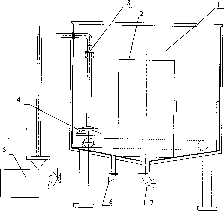
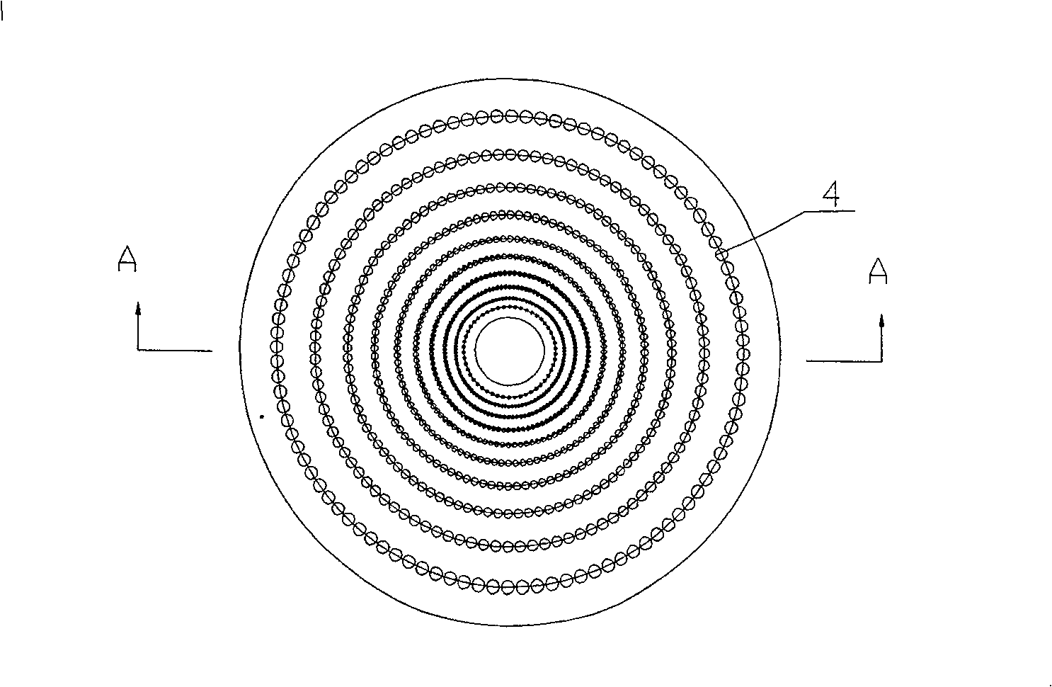
[0029] Such as figure 1 , 2 As shown, the aeration-type convective mixed deinking flotation cell includes a deinking cell body 1, an ink collection tank 2, a slurry inlet pipe 3, an aeration element 4, a slurry pump 5, a good slurry outlet 6, and an ink outlet 7. The ink collection tank 2 is welded in the tank body 1 and is located in the middle of the tank body 1. Between the outer periphery of the ink collection tank 2 and the inner wall of the deinking tank body 1, there are I-1, I-2, I-3, I-4 and I -5 consists of 5 stages of flotation zones, and II-1 is the last flotation zone, which can be used as the sixth stage flotation zone or ink fiber recovery zone according to actual needs. Each flotation zone is provided with an aeration element 4, a slurry inlet pipe fitting 3 and a spray h...


PUM


Abstract

The invention discloses an aeration-type countercurrent- mixing deinking floatation cell, comprising deinking groove body, printing ink collecting cell, pulp inlet pipe fitting, aeration component, pulp pump, good pulp outlet, and printing ink outlet, where the aeration component comprises aeration diaphragm, fan and connecting pipe, the aeration diaphragm is densely distributed with 0.2-1 mm small holes and connected with the fan through the connecting pipe; the pulp inlet pipe fitting comprises pulp pipe, bend, steel pipe and regulating flange, the pulp pipe is welded through the bend onto the steel pipe with somewhat larger diameter, the steel pipe is connected with the regulating flange, the regulating flange is connected through the pulp pipe with a pulp spray nozzle. And it adopts highly regulable pulp inlet pipe fitting and diaphragm aeration component and makes countercurrent mixing of air bubbles and pulp, thus increasing the possibility of air bubbles capturing printing ink particles and improving floatation deinking effect. And it has characters of low energy consumption, compact structure, simple flow, a complete set of easy-to-manufacture equipment, and suitable for small and medium-size waste paper deinking factories.

Description

technical field [0001] The invention relates to the field of pulping and papermaking equipment and technology, in particular to an aeration type convection mixing deinking flotation tank. Background technique [0002] With the increasing demand for raw materials in the paper industry and the improvement of environmental protection requirements, waste paper, as a convenient, economical and less polluting fiber raw material, has been increasingly valued by the paper industry. Making full use of waste paper resources is an important measure to adjust the structure of papermaking raw materials. Deinked pulp is mainly used in the production of newsprint, cultural printing paper, etc. In recent years, the progress of waste paper deinking technology has made great progress in the production of deinked pulp. In the deinking process of waste paper, the flotation cell is the most critical core equipment. The flotation cell is based on the hydrophobic characteristics of most printing...

Claims


Application Information

Patent Timeline
Patent Type & Authority Patents(China)
IPC IPC(8): D21C5/02
CPCY02W30/64
Inventor 陈克复官日彬陈奇峰李军李擘李荣刚
Owner SOUTH CHINA UNIV OF TECH
Learn More