
Floatation column for mineral separation

A mineral separation and flotation column technology, applied in flotation, solid separation, etc., can solve the problems of unsatisfactory equipment utilization, unbalanced feed and discharge, and inability to automatically control discharge, etc., to facilitate the industrialization of PLC Control, Versatile, and Small Footprint Effects

Inactive Publication Date: 2009-11-25
湖南君毅科技发展有限公司
View PDF2 Cites 0 Cited by
  • Summary
  • Abstract
  • Description
  • Claims
  • Application Information

AI Technical Summary

Problems solved by technology

The defects of the existing structure are: (1) the clean coal from flotation is discharged from one point to the same direction by the electric pump, which is not easy to grasp and control the balance of the clean coal tank above the column; (2) the tailings are collected and discharged Automatic overflow, but can not automatically control the discharge, so that the feed and discharge can not be balanced, which will affect the overall balance; even pipe blockage will occur, which will affect the flotation efficiency; (3) The design of the mixed coal slurry in the middle of the sorting barrel It is pumped by a single circulation pump into the multi-point circulation of the mineralizer at the top of the flotation column, and its repeated separation speed is slow, inconvenient to adjust, and the efficiency is not high; The implementation of the system plays the role of air inflation and pressure supplementation, but for the automatic discharge of clean coal and liquid level adjustment, the automatic collection and discharge of tailings have no direct correlation effect, so the overall automation control is not high, the utilization rate of equipment is not very ideal, and the energy consumption also larger

Method used


Image

  • Floatation column for mineral separation

Examples


Embodiment Construction

[0026] The present invention will be described in further detail below in conjunction with the accompanying drawings and specific embodiments.

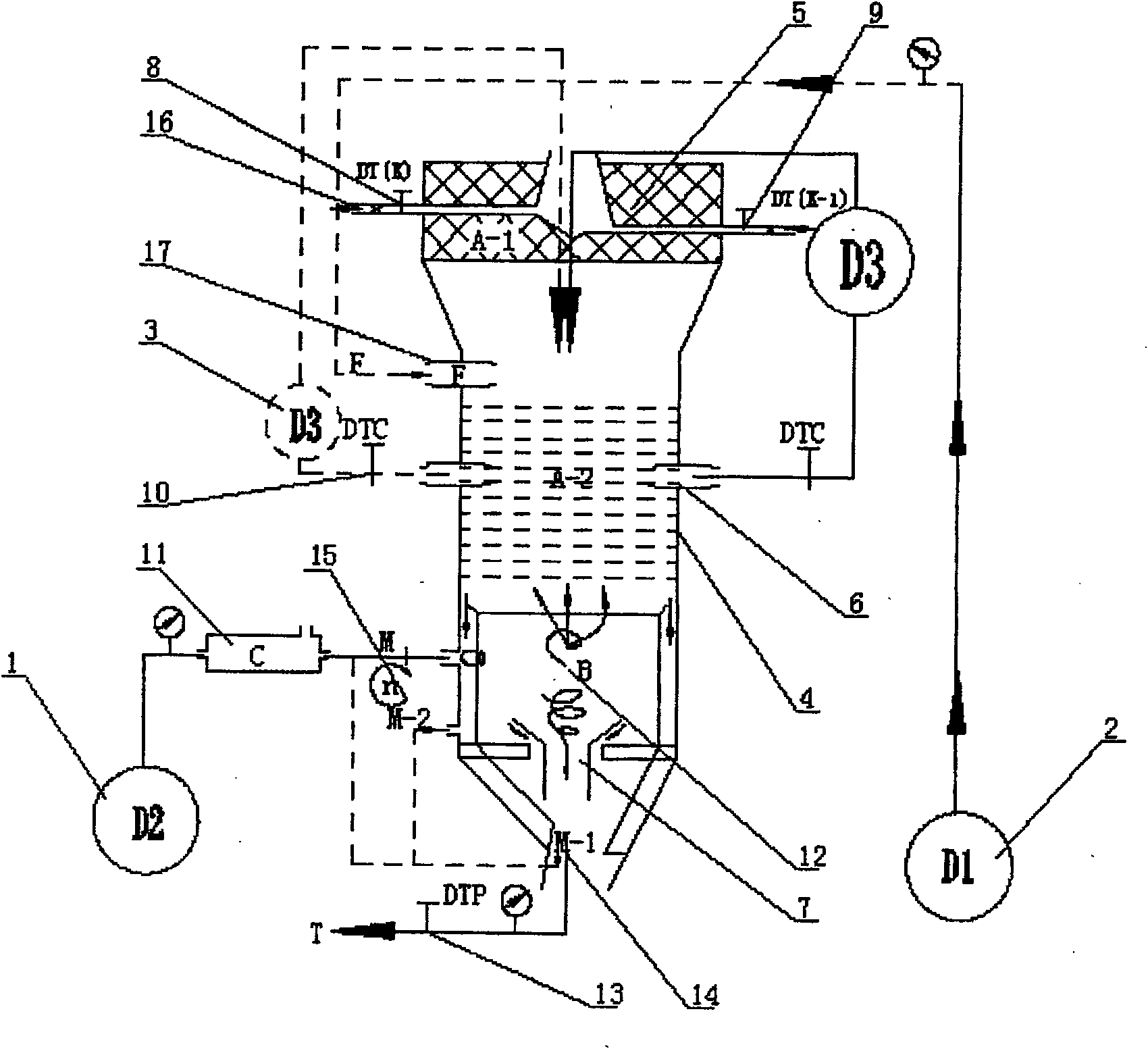
[0027] see figure 1 Shown, a kind of flotation column that is used for mineral separation of the present invention, it comprises column body 4, and described column body 4 is successively divided into concentrate collecting tank 5, sorting barrel and tailings discharge in the column body 4 Box 7, the concentrate collection tank 5 is provided with more than one concentrate discharge port 16, the concentrate discharge port 16 is provided with a concentrate discharge electric solenoid valve that can adjust the liquid level, and the sorting barrel includes The static micro-bubble sorting section in the middle and the swirling flow sorting section in the lower part, the sorting barrel is connected with the external air pump 1, the sorting barrel is equipped with a column inner cyclone 12, and the tailings discharge box 7 bottom tailings di...


PUM


Abstract

A flotation column for mineral separation, characterized in that it includes a column body, which is divided into a concentrate collection tank, a sorting barrel, and a tailings discharge box from top to bottom in sequence, and the concentrate There is more than one concentrate discharge port on the collection tank, and the concentrate discharge port is equipped with a concentrate discharge electric solenoid valve that can adjust the liquid level. In the sorting section, the sorting barrel is connected with the external air pump, and the sorting barrel is equipped with a column inner cyclone, and the tailings discharge port at the bottom of the tailings discharge box is equipped with an automatic valve linked with the concentrate discharge electric solenoid valve. Dump valve. The invention is a flotation column for mineral separation with simple and compact structure, low cost, high efficiency and energy saving, small floor space, long service life, fast flotation speed and large processing capacity.

Description

technical field [0001] The present invention mainly relates to the field of mineral separation equipment, in particular to a flotation column for mineral separation, which can not only be used for flotation of coal slime in (fine) fly ash whose middle diameter is -0.5MM particle size and below. It can also be widely used in coal slime recovery and graphite chemical industry in large, medium and small coal preparation plants, and can also be used in flotation of other metals and non-metals. Background technique [0002] With the development of the national economy, the extensive resource development model of "high development, low utilization, and high emission" has gradually restricted the resource recovery rate and resource recycling rate. In the long run, this will inevitably lead to the scarcity of natural resources, energy shortage and environmental pollution, and the development of mineral resources is facing great challenges. Flotation column has shown strong vitality...

Claims


Application Information

Patent Timeline
Patent Type & Authority Patents(China)
IPC IPC(8): B03D1/14
Inventor 郭宇徐梓毅肖谷金周泰径
Owner 湖南君毅科技发展有限公司
Learn More