
Six-five axis spiral awl gear cutting machine

A technology of spiral bevel gears and machine tools, which is applied in metal processing machinery parts, metal processing equipment, belts/chains/gears, etc., can solve the problem of insufficient use of numerical control technology, complex shape of workpiece box 41, and poor processing manufacturability. and other problems, to achieve the effect of compact structure, small footprint and good stress condition

Inactive Publication Date: 2007-08-15
HUNAN ZDCY (ZHONGDA CHUANG YUAN) CNC EQUIP CO LTD
View PDF0 Cites 33 Cited by
  • Summary
  • Abstract
  • Description
  • Claims
  • Application Information

AI Technical Summary

Problems solved by technology

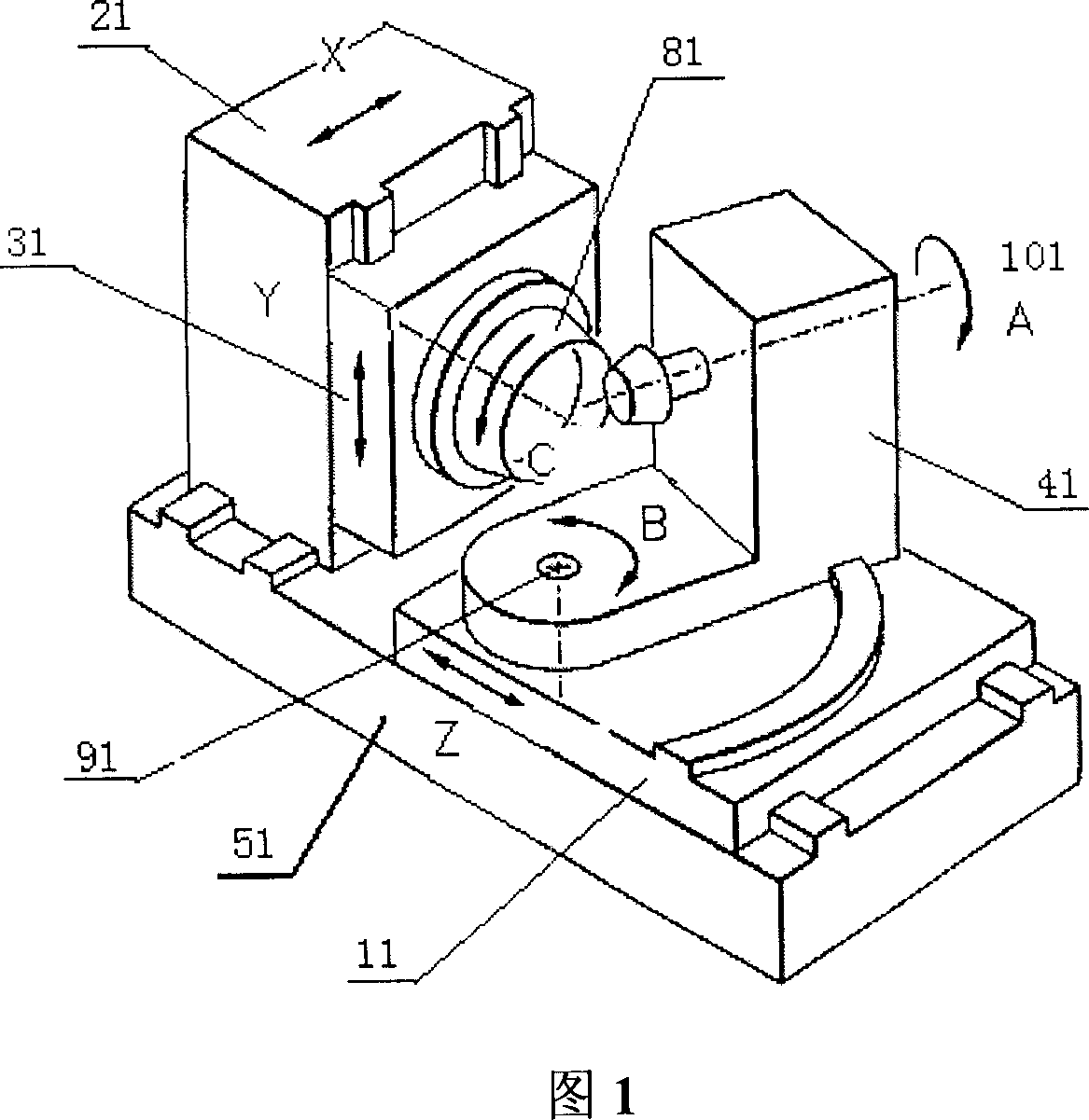
However, the above-mentioned equipment is a kind of intentionally simulating the structure of a mechanical machine tool. The rotation mechanism of the cradle is changed to the linkage of X and Y axes to realize the rotation of the tool around the axis of the cradle, and the function of the tool tilt mechanism is changed to the swing of the B axis. The role of numerical control technology has not been fully utilized, so there are still the following main defects:
[0003] 1. There is a sector gear or friction wheel with a large diameter on the Z-axis sliding table 11 in the Z direction of the linear axis, and the processing technology is not good;
[0004] 2. The shape of the workpiece box 41 is complicated, the manufacturability of processing is not good, and it is difficult to guarantee the processing accuracy;
[0005] 3. All the weight of the workpiece box 41 is pressed on the sector gear or the friction wheel, so it is difficult to unload;
[0006] 4. The X-axis sliding table 21 in the X direction of the linear axis is a gantry, and the Y-axis sliding table 31 in the Y direction of the linear axis moves vertically on the gantry. The servo motor and the hydraulic balance cylinder are erected very high, and the protection is very difficult;
[0007] 5. For the sake of environmental protection and saving, the development direction of spiral bevel gear milling is dry cutting, that is, no coolant is added during processing, the cutting speed is very fast, and the heat is taken away by chips, which requires that hot chips cannot fall on the bed. , so as not to affect the thermal deformation of the machine tool, the device in Fig. 1 is difficult to do this;
[0008] 6. The machine tool has many parts and occupies a large area, so it is inconvenient to load and unload the workpiece

Method used


Image

  • Six-five axis spiral awl gear cutting machine
  • Six-five axis spiral awl gear cutting machine

Examples


Embodiment Construction

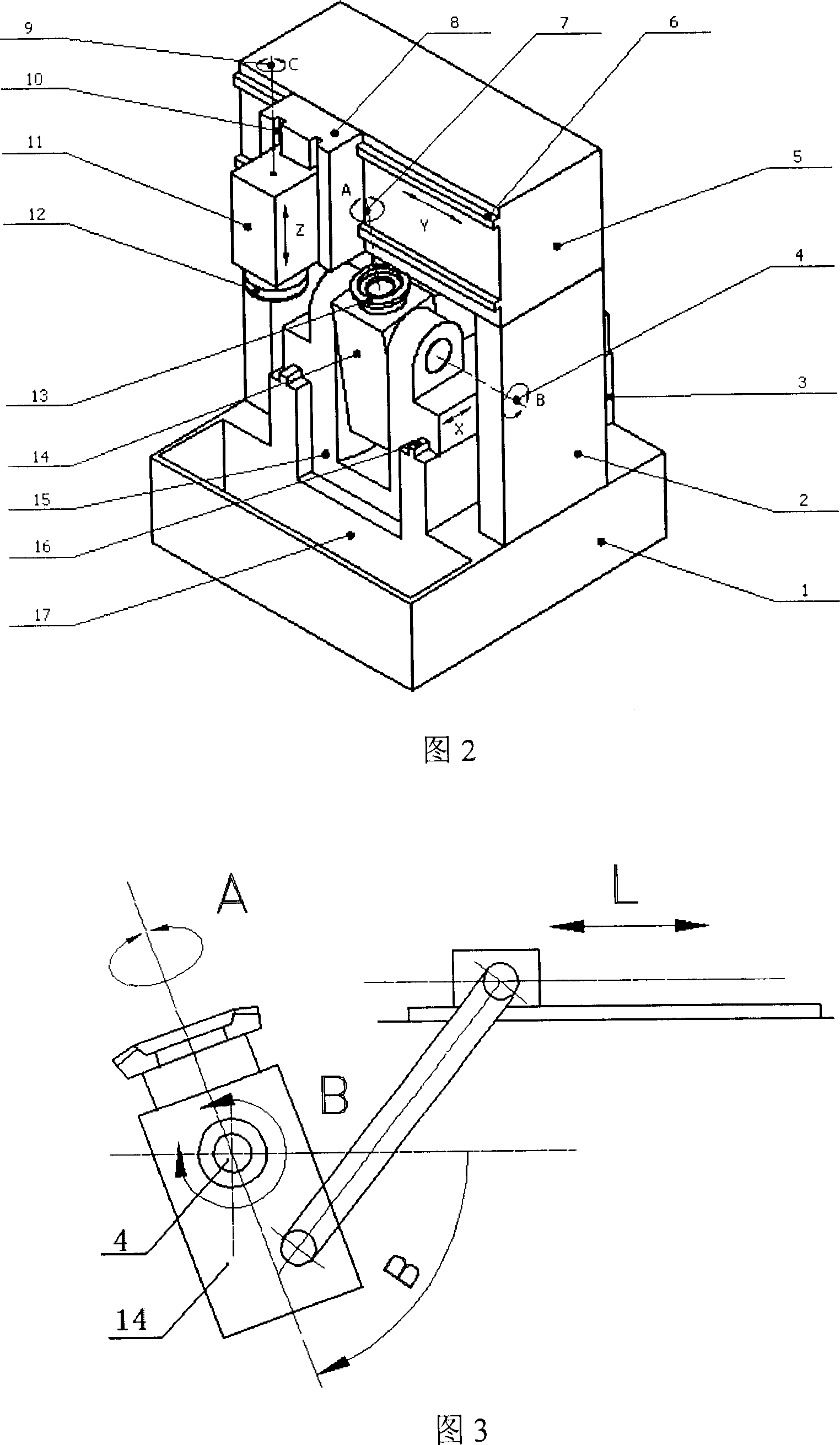
[0045] According to Figure 2 and the machine tool with the above structure, the three linear guides and the sliding drive mechanism adopt rolling guides and ball screws, and the servo motor transmits the rotation of the motor to the ball screws through a direct connection or a reduction device, driving the X-axis to slide The table, workpiece box and Z-axis sliding table move (of course, it can also be directly driven by a linear motor); the displacement of the X-axis, Y-axis and Z-axis is measured by a grating ruler, and the closed-loop control is used; the rotation of the A-axis is preferably directly driven by a high-torque motor , its rotation angle is measured by a high-precision grating disc and closed-loop controlled. The tool axis C is also preferably directly driven by an electric spindle or a torque motor; the rotation of the B-axis can be directly driven by a high-torque motor, or indirectly driven by a connecting rod mechanism as shown in Figure 3, and its rotation ...


PUM


Abstract

The invention relates to a six-axle five-linkage screw taper gear turning machine, wherein two sides of the machine are arranged with posts, a beam is mounted at the top of the posts, the middle of the machine is disposed with a X-track engaged with a movable X-axle block, one side of the beam is arranged with a Y-track with a movable Y-axle block, the Y-axle block is arranged with a Z-track with a movable Z-axle block mounted with a tool box, the tool box rotates driven by a driver and is mounted with a C axle with blades, the X-axle block is mounted with a work-piece box arranged with A axle for rotating and mounting work-piece driven by the driver, the work-piece box via B axle is hinged on the X-axle block and rotates around B axle. The invention has simple structure, high stability and efficiency.

Description

technical field [0001] The invention relates to numerical control processing equipment, and further refers to a numerical control milling machine and a gear grinding machine for processing spiral bevel gears. Background technique [0002] In the prior art, the structure and adjustment links of mechanical spiral bevel gear processing machine tools are the most complicated among gear machine tools. With the advancement of technology, the spiral bevel gear processing machine tool adopts the structure shown in Figure 1, which uses a computer to directly control three linear axes (ie X, Y, Z axes) and three rotational axes (ie A, B, C axes) , that is, the machining motion of the mechanical spiral bevel gear processing machine can be simulated, so as to process the spiral bevel gear. The CNC spiral bevel gear processing machine tool converts the complex mechanical structure into software control, realizing the informatization and intelligence of spiral bevel gear processing. How...

Claims


Application Information

Patent Timeline
Patent Type & Authority Applications(China)
IPC IPC(8): B23F9/00B23F9/10B23F9/02B23Q1/26
Inventor 曾韬
Owner HUNAN ZDCY (ZHONGDA CHUANG YUAN) CNC EQUIP CO LTD
Learn More