Highly efficient energy-saving reversion circuit

A technology of inverter circuit and half-bridge inverter circuit, which is applied to electrical components, conversion devices for converting AC power input to DC power output, and output power, etc. question

Inactive Publication Date: 2007-08-15
GUANGDONG ZHICHENG CHAMPION GROUP
View PDF0 Cites 2 Cited by
  • Summary
  • Abstract
  • Description
  • Claims
  • Application Information

AI Technical Summary

Problems solved by technology

[0003] At present, the inverters produced by various manufacturers mostly use double-tube half-bridge drive and four-tube full-bridge circuit structure. Using these two working methods has low working efficiency, and the maximum is only about 90%, and nearly ...

Method used


Image

  • Highly efficient energy-saving reversion circuit
  • Highly efficient energy-saving reversion circuit

Examples


Embodiment Construction

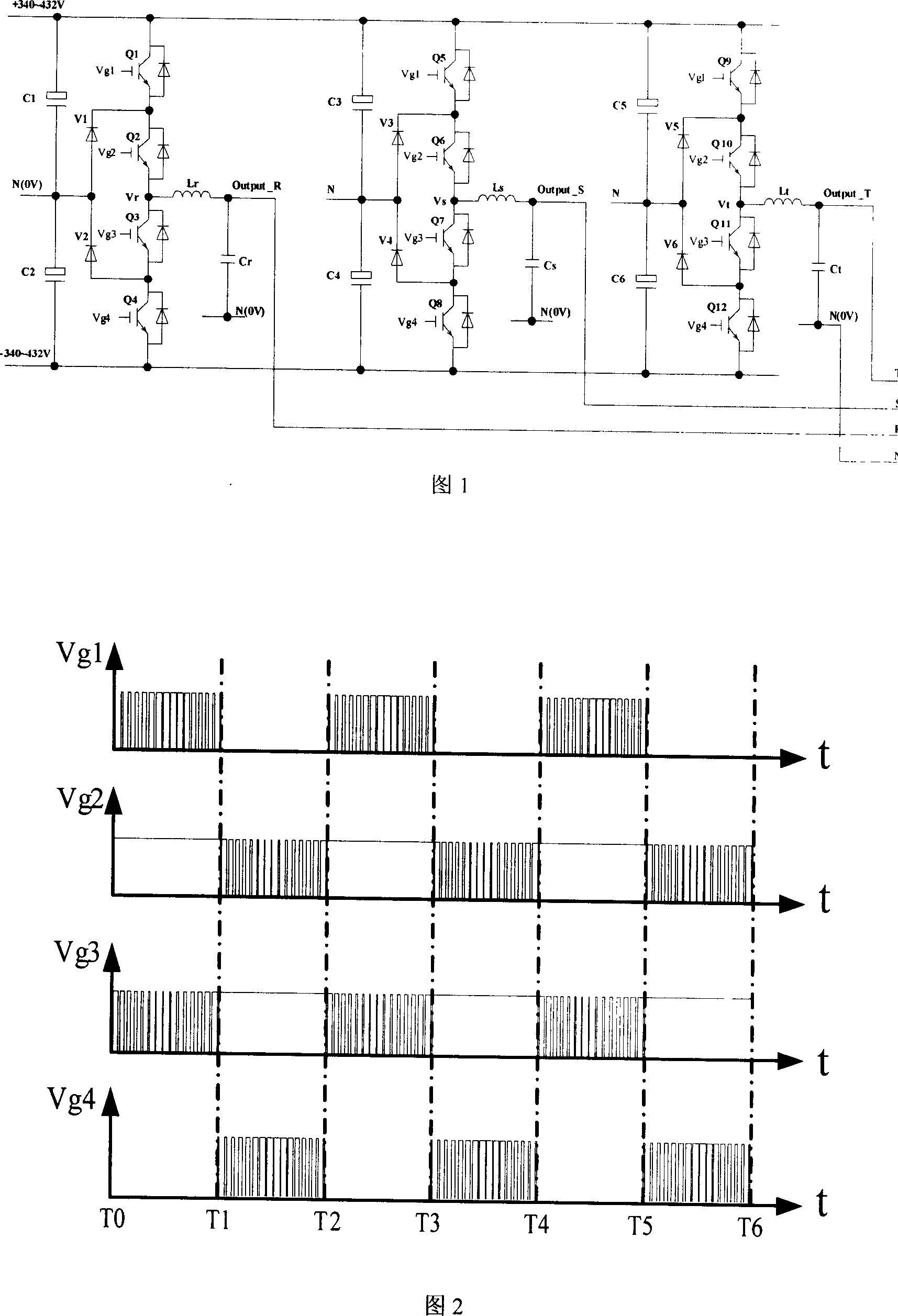
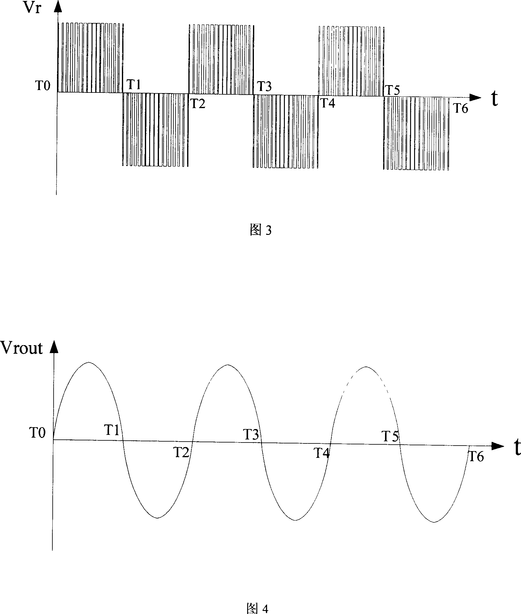
[0014] The high-efficiency and energy-saving inverter circuit of the present invention has a circuit structure as shown in Figure 1, which is composed of three four-tube half-bridge inverter circuits, and the three four-tube half-bridge inverter circuits are connected in parallel between positive and negative DC power supplies. Each four-tube half-bridge inverter circuit completes the generation of one-phase alternating current, and the sine waves generated between the phases differ by 120 degrees, thus forming a three-phase sine wave output.

[0015] Now take the R phase as an example to describe its circuit composition and working principle:

[0016] The four-tube half-bridge inverter circuit includes 4 power tubes (IGBT) Q1-Q4, 2 fast recovery diodes V1-V2 and an output filter circuit. The collector of the power tube Q1 is connected to the positive pole of the DC power supply, and the emitter is connected to the power tube Q2. The collector of the power tube Q2 is connected...


PUM


Abstract

The disclosed high-efficient saving-energy inversion circuit comprises: a power tube, a recovery multi-diode, and an output filter circuit to form together into a single phase four-tube semi-bridge inversion circuit, or three-phase four-tube semi-bridge inversion circuit. Wherein, it sets drive voltage in a period not always carrier frequency, while half-period wave is constant past or broken. Compared with prior art, thereby, this invention reduces switch frequency so as the switch tube loss as half of original, then increases inversion efficiency, and adds power density.

Description

technical field [0001] The invention relates to an inverter circuit, in particular to a high-efficiency and energy-saving inverter circuit, which can be widely used in UPS power supplies, sine wave inverters, frequency converters and other occasions requiring DC / AC conversion. Background technique [0002] The function of the sine wave inverter is to convert the constant DC voltage into an alternating sinusoidal voltage, which is suitable for the use of AC-powered equipment. High efficiency and low harmonic distortion are often the key technical indicators of this technology. [0003] At present, the inverters produced by various manufacturers mostly use double-tube half-bridge drive and four-tube full-bridge circuit structure. Using these two working methods has low working efficiency, and the maximum is only about 90%, and nearly 10% of the electric energy is converted into The loss of heat energy will increase the heat dissipation cost and reduce the power density, which ...

Claims


Application Information

Patent Timeline
IPC IPC(8): H02M7/537
Inventor 周志文李民英
Owner GUANGDONG ZHICHENG CHAMPION GROUP
Why Eureka
Try Eureka