Sinter-smoke circulation collected desulfurizing method and apparatus

A technology for sintering flue gas and desulfurization devices, applied in the field of desulfurization devices, can solve the problems of large flue gas treatment capacity, large engineering investment, and high operating costs, and achieve the effects of saving operating costs, saving engineering investment, and improving desulfurization efficiency

Inactive Publication Date: 2007-08-29
ZHONGYE-CHANGTIAN INT ENG CO LTD
View PDF0 Cites 59 Cited by
  • Summary
  • Abstract
  • Description
  • Claims
  • Application Information

AI Technical Summary

Problems solved by technology

The existing problems of this desulfurization method are: large amount of flue gas treatment, resulting in large project investment and high operating costs; 2 Low concentration leads to low desulfurization efficiency

Method used


Image

  • Sinter-smoke circulation collected desulfurizing method and apparatus
  • Sinter-smoke circulation collected desulfurizing method and apparatus

Examples


Embodiment 1

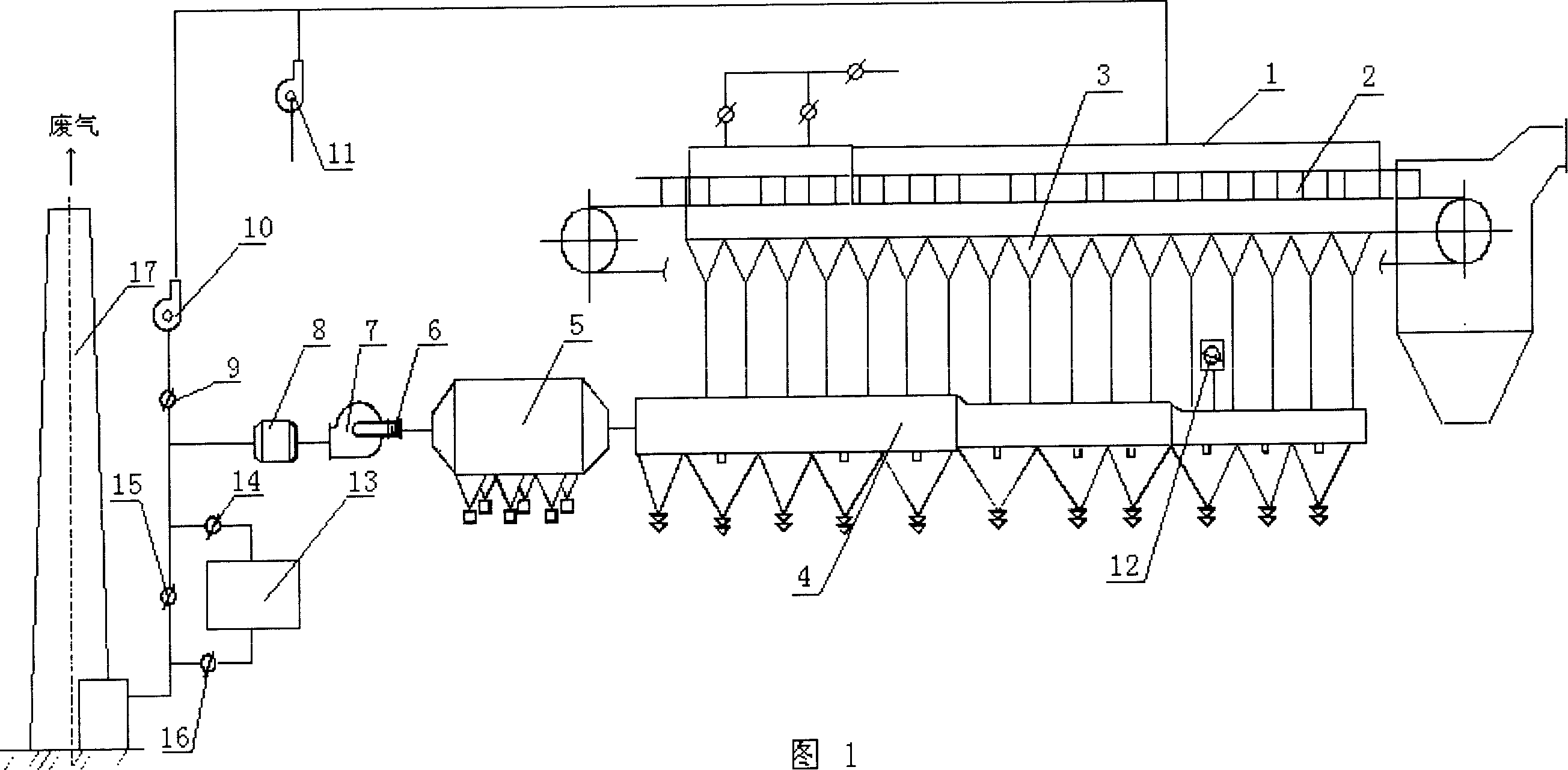
[0023] The sintering flue gas cycle enrichment desulfurization method for single flue is: take about 50% of the flue gas from the flue of the sintering machine and return it to the upper sealing cover of the sintering machine for circulation, and at the same time supplement the oxygen required for the combustion of the sintering machine, The rest of the flue gas is discharged after desulfurization treatment.

Embodiment 2

[0025] As shown in Figure 1. The sintering flue gas circulation enrichment desulfurization device for single flue includes sintering machine sealing cover 1, sintering machine trolley 2, sintering machine bellows 3, sintering machine large flue 4, dust collector 5, fan inlet regulating valve 6, main Exhaust fan 7, muffler 8, flue baffle switching valve 9, circulation fan 10, oxygen supply fan 11, cold air suction valve 12, flue baffle switching valve 14, flue baffle switching valve 15, flue baffle switching Valve 16, desulfurization process device 13 (existing desulfurization process devices can be used, including wet, dry and semi-dry methods of calcium method, ammonia method, organic amine method, seawater method and other process devices), chimney 17. A sealing cover 1 is added to the upper part of the sintering machine trolley 2, the lower part of the trolley 2 is connected to the bellows 3 of the sintering machine, the bellows 3 are collected to the flue 4, the cold air s...

Embodiment 3

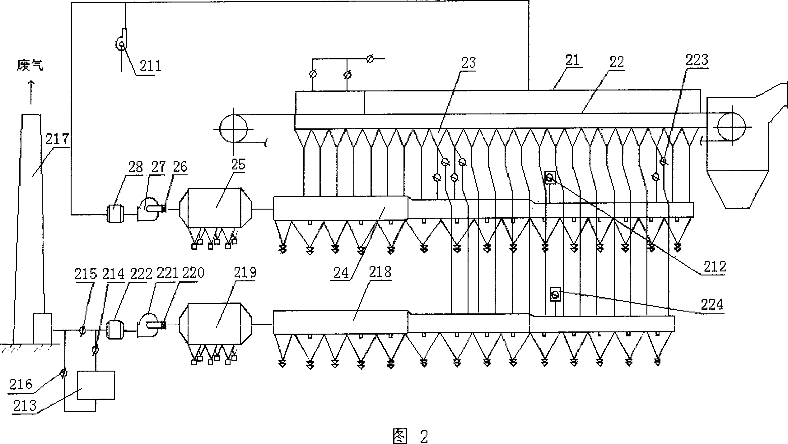
[0028] The sintering flue gas circulation enrichment desulfurization method for double flue is as follows: the sintering machine uses two flues, and one flue takes a part of low-concentration SO from the head and tail wind boxes of the sintering machine. 2 The flue gas returns to the sealed cover on the upper part of the sintering machine for circulation, and at the same time supplements the oxygen required for the combustion of the sintering machine, and uses another flue to reduce the high concentration of SO in the middle wind box of the sintering machine 2 The flue gas is discharged after desulfurization treatment.


PUM


Abstract

The invention discloses a sintering flue gas desulfurization cycle enrichment methods and device, the described method from the sintering machine take part gas return to the top of sintering machine sealed enclosures within cycle, while complementing sintering machine burning need oxygen, the remaining part of the flue gas discharge after desulfurization. In devices, including dedusting device of flue gases between the chimney and flue, in the road before the desulfurization setup a branch pipeline to connect sintering machine sealed enclosures, in the branches of pipe setup cycle fan and supplement device. This invention due to sintered exhaust gas partly return to the seal trolley of sintering machine to reduce the displacement of gas, thereby reducing the total of dust and exhaust gas, while the SO2 of the sintering process play a enrichment role, to increase desulfurization efficiency, and reduce release total of burning exhaust gas, reducing the processing load of desulfurization device.

Description

technical field [0001] The invention belongs to a desulfurization device, and in particular relates to a method and a device for circular enrichment and desulfurization of sintering flue gas of a sintering machine in the metallurgical industry. Background technique [0002] The existing sintering process in the iron and steel metallurgical industry generally adopts negative pressure ventilation sintering process, so there is a large amount of sintering flue gas emission, SO 2 Low concentration and other characteristics, resulting in large project investment, high operating costs and difficult to handle. [0003] The sintering plants of a few domestic iron and steel enterprises have adopted flue gas desulfurization treatment measures for the sintering flue gas of small sintering machines, that is, installing flue gas dedusting and desulfurization devices between the flue and the chimney that collect the flue gas of the sintering machine (can be used Existing desulfurization ...

Claims


Application Information

Patent Timeline
Patent Type & Authority Applications(China)
IPC IPC(8): B01D53/50F27B21/08F27D17/00
Inventor 储太山刘昌齐叶恒棣陈乙元何国强梁段萍
Owner ZHONGYE-CHANGTIAN INT ENG CO LTD
Why Eureka
Try Eureka