Multi-channel microwave power synthesizer for analog/digital TV transmitter

A microwave power and synthesizer technology, applied in color TV parts, TV system parts, TV and other directions, can solve the problems of inability to effectively meet high-power synthesis, synthesis circuit damage, etc., and achieve easy amplitude and phase balance, The effect of avoiding power loss and facilitating connection

Inactive Publication Date: 2007-09-12
杭州南广科技有限公司
View PDF1 Cites 4 Cited by
  • Summary
  • Abstract
  • Description
  • Claims
  • Application Information

AI Technical Summary

Problems solved by technology

This technical scheme is the first to adopt the combination of stripline and microstrip line, which has good consistency in power synthesis, and is easy to process, and can be applied to small and medium-sized power synthesis; however, due to the use of printed circuit board and microstrip line structure, In the application process, it is limited by its own power and cannot effectively meet the needs of high-power synthesis, which can easily lead to damage to the synthesis circuit.

Method used


Image

  • Multi-channel microwave power synthesizer for analog/digital TV transmitter
  • Multi-channel microwave power synthesizer for analog/digital TV transmitter
  • Multi-channel microwave power synthesizer for analog/digital TV transmitter

Examples


Embodiment 1

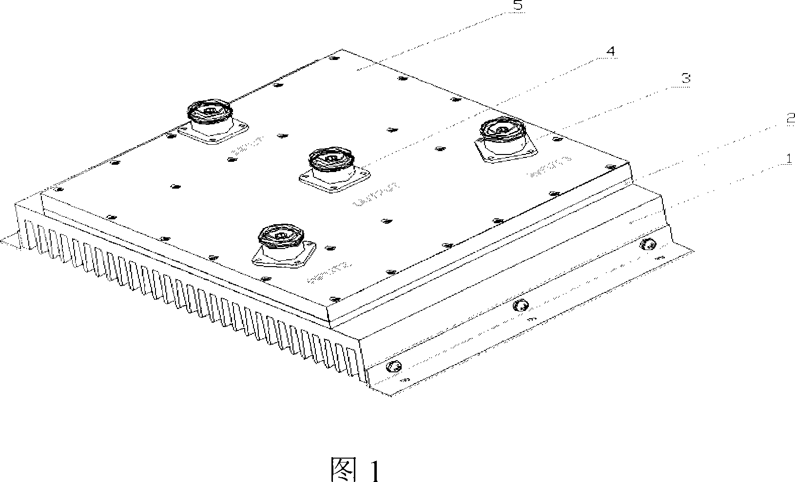
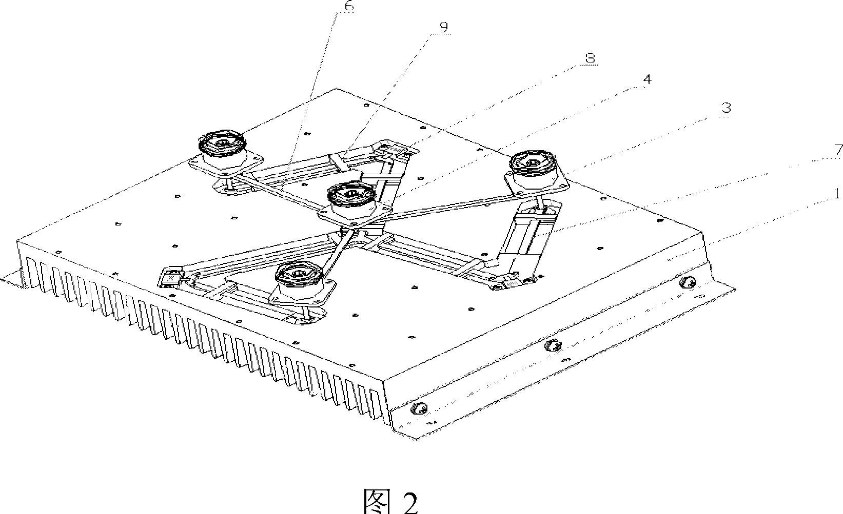
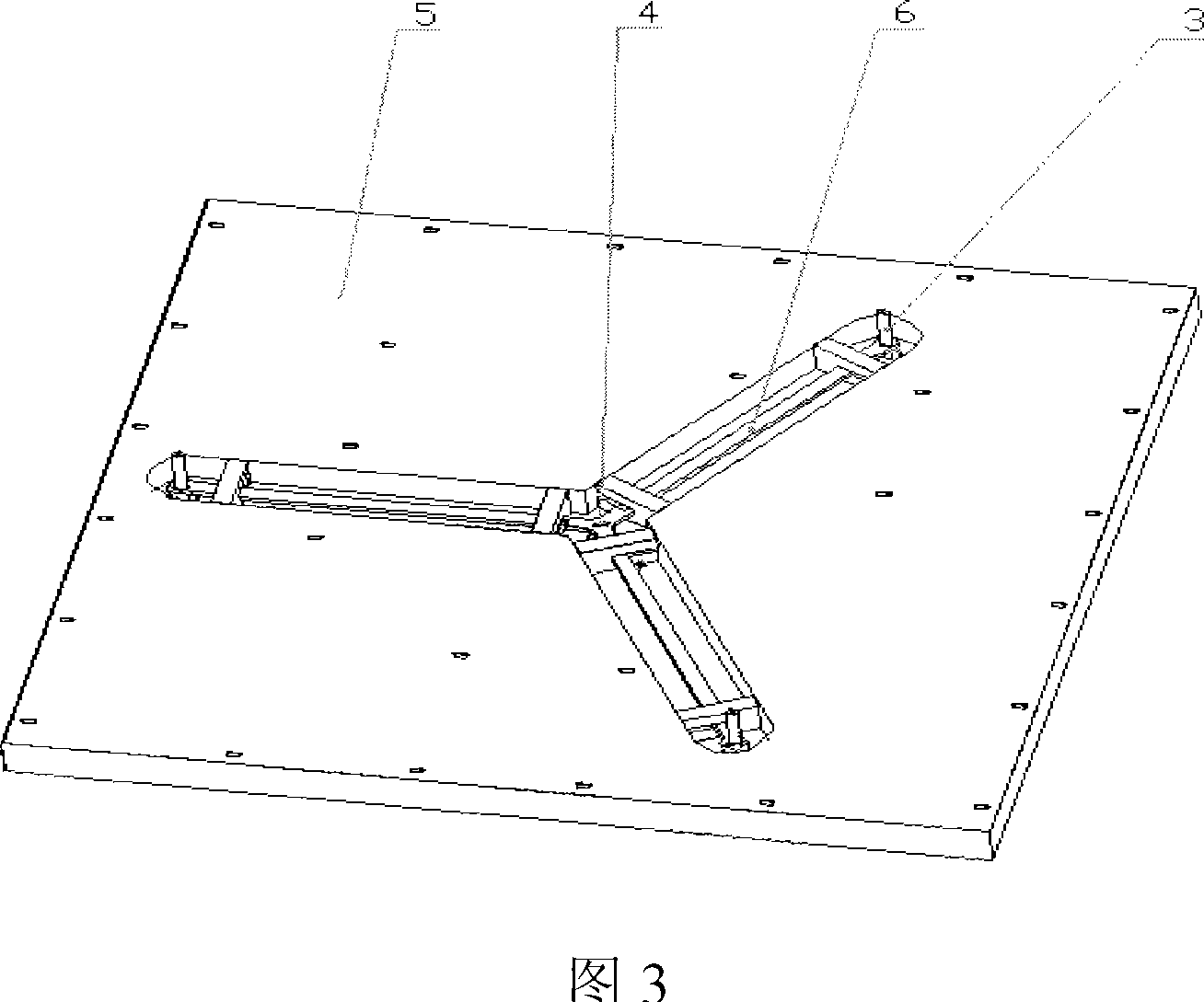
[0028] As shown in Figure 1, Figure 2, Figure 3, and Figure 4, a multi-channel microwave power combiner includes a base plate 1, a middle cover plate 2, an input connector 3, an output connector 4, an upper cover plate 5, and power combining Stripline 6, Balanced Stripline 7, Balanced Resistor 8, Insulation Mat 9. The signal to be synthesized is input from the input connector 3, and then converged to the output of the connector 4 after passing through each branch of the power synthesis strip line 6. The heat generated by the device is mainly volatilized through the heat dissipation base plate 1, and the upper cover plate 5 can effectively shield The electromagnetic relationship between the power combining stripline 6 and the outside world. The balanced stripline 7 and the balanced resistor 8 are mainly used to optimize various parameters of the circuit, including working bandwidth, input-output matching, isolation, amplitude balance, phase balance and so on.

[0029] Fig. 3 i...

Embodiment 2

[0032] As shown in Fig. 6 and Fig. 7, it is a four-way synthesizer. Like the embodiment (1), both the synthesis circuit and the balance circuit use striplines, which can meet the requirements of obtaining larger power capacity while reducing the volume. Figure 6 shows a composite stripline group. The line width needs to be calculated according to the characteristic impedance determined by the number of currently synthesized lines, and the length of each line is a quarter of the working wavelength. Figure 7 shows the balanced stripline group. Four striplines with one-half working wavelength are bent to form a common potential through a common point. A 50-ohm balance resistor is also required to be connected to the quarter-line length. The connection between the balanced stripline and the synthesized stripline is consistent with the method of embodiment (1).

[0033] Because all the stripline branches are distributed in a circle with equal radius, the size of the required alumin...


PUM


Abstract

The invention is a multichannel microwave power synthesizer for analog / digital TV transmitter, comprising baseplate, middle plate and top cover plate, which are all of a one-piece metal substrate; the right side of the top cover plate is equipped with a group of input connectors and an output connector at intervals, where the input connectors are located on an equi-radius circle with the output connector as the center; the back of the top cover plate, the two sides of the middle plate and the right side of the baseplate are all made with milled grooves, combinationally composing the cavity part of inner conductor transmission lines, and the baseplate and heat radiator are integrally designed. As compared with the existing techniques, it has advantages of easy to make, good synthesis performance, and good heat radiating effect, and especially applied to high power synthesis.

Description

technical field [0001] The invention relates to a power combiner, in particular to a multi-channel microwave power combiner for analog / digital television transmitters. Background technique [0002] The basis for the development of all solid-state technology for TV transmitters is the continuous progress of VHF and UHF solid-state device manufacturing technology. In order to improve efficiency, the all-solid-state power amplifier adopts Class A and B linear amplification methods, but the output capacity of a single tube is limited. To increase the power level of the transmitter, only the method of parallel operation of multiple tubes can be used, but the parallel connection of multiple tubes requires multi-stage power. Synthesis can form a power amplifier with a certain power level. This technology of superimposing the output power of multiple devices is the power combining technology. The use of power combining technology can improve the reliability of the output device, r...

Claims


Application Information

Patent Timeline
Patent Type & Authority Applications(China)
IPC IPC(8): H04N5/40H04N5/38H01P1/213
Inventor 潘国平方昭敏许佳
Owner 杭州南广科技有限公司
Why Eureka
Try Eureka