Magnetic recording medium and a method of manufacturing the same

一种磁记录介质、磁记录层的技术,应用在磁记录、磁记录层、数据记录等方向,能够解决大量加工时间、复杂、磁性质劣化等问题

Inactive Publication Date: 2007-09-26
FUJI ELECTRIC DEVICE TECH CO
View PDF8 Cites 3 Cited by
  • Summary
  • Abstract
  • Description
  • Claims
  • Application Information

AI Technical Summary

Problems solved by technology

However, this process requires a lot of processing time
In addition, it is difficult to achieve a size of each dot smaller than 30nm with sufficient precision
One problem that arises in the processing of magnetic films is the deterioration of magnetic properties due to thermal damage
It is difficult to be compatible with minimization and regular arrangement when forming nanopores under the current state of the art
In addition, the process is complicated by the need to planarize the surface after filling the holes with magnetic material
[0016] Therefore, as mentioned above, the proposed techniques for forming dots in patterned media are all complicated and there are many problems in the manufacture of patterned media

Method used


Image

  • Magnetic recording medium and a method of manufacturing the same
  • Magnetic recording medium and a method of manufacturing the same
  • Magnetic recording medium and a method of manufacturing the same

Examples


Embodiment 1

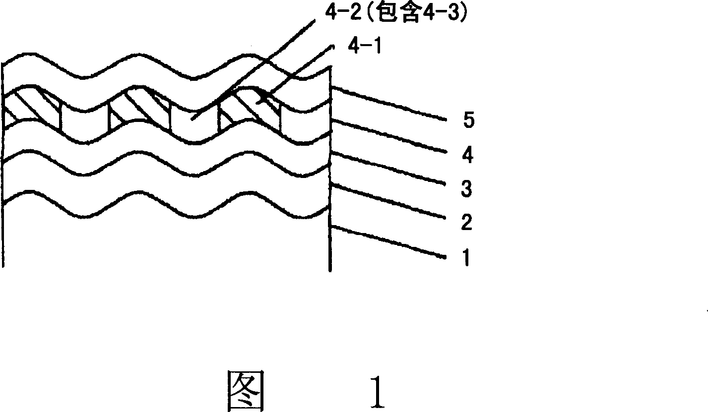
[0064] The non-magnetic substrate 1 is a disk-shaped silicon substrate whose smooth surface has a surface roughness Ra=0.5 nm. After the substrate is cleaned, the substrate is introduced into the EB equipment for wire processing on the surface of the substrate. When this processing is performed, the position of the electron beam is fixed and the substrate is moved radially and horizontally while rotating the substrate to form concentric circles. The spacing between the ridge lines is controlled to be 25 nm, and the height difference between the top line and the bottom line of the wave structure is controlled to be 10 nm. Then, the substrate was introduced into the sputtering equipment and sprayed with Co 92 Zr 5 Ta 3 The target forms a soft magnetic backing layer 2 of amorphous CoZrTa with a thickness of 100 nm. Subsequently, a ruthenium underlayer 3 was deposited with a ruthenium target at 3 mTorr argon pressure to a thickness of 5 nm. Then, using (Co 80 Pt 20 ) 90 (S...

Embodiment 2

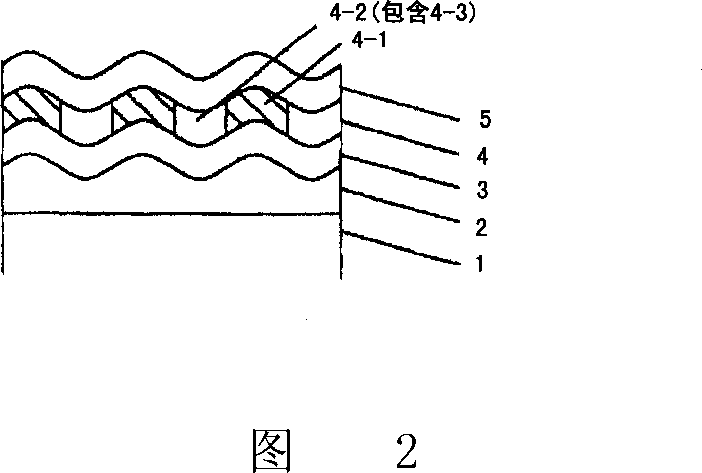
[0066] The same non-magnetic substrate 1 as in Example 1 was used. After cleaning, the substrate was introduced into a sputtering device, and a soft magnetic backing layer 2 of CoZrTa with a thickness of 100 nm was formed in the same manner as in Example 1. The substrate is introduced into EB equipment, and line processing is performed on the surface of the soft magnetic backing layer 2 . In the same manner as in Example 1, concentric circles were formed during the line processing. The spacing between the ridge lines was controlled to 25 nm, and the difference between the heights of the top and bottom lines of the wave structure was controlled to 3 nm. Afterwards, in the same manner as in Example 1, the ruthenium lower layer 3, CoPt-SiO 2 Magnetic recording layer 4, carbon protective layer 5 and liquid lubricating layer. Thus, the magnetic recording layer of Example 2 was produced.

Embodiment 3

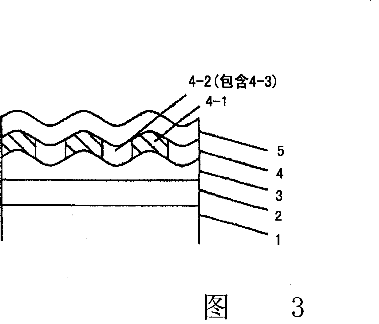
[0068] The same non-magnetic substrate 1 as in Example 1 was used. After cleaning, the substrate was introduced into a sputtering device, and a soft magnetic backing layer 2 of CoZrTa with a thickness of 100 nanometers and a ruthenium lower layer 3 with a thickness of 5 nanometers were formed in the same manner as in Example 1. The substrate is introduced into the EB equipment, and wire treatment is performed on the surface of the ruthenium lower layer 3 . In the same manner as in Example 1, concentric circles were formed during the line processing. The spacing between the ridge lines is controlled to 25 nm, and the height difference between the top line and the bottom line of the wave structure is controlled to 3 nm. Thereafter, the magnetic recording layer 4, the protective layer 5, and the liquid lubricating layer were sequentially formed in the same manner as in Example 1. Thus, the magnetic recording layer of Example 3 was produced.


PUM

PropertyMeasurementUnit
particle diameteraaaaaaaaaa

Abstract

The present invention provides a magnetic recording medium having magnetic dots that can achieve high density recording is disclosed. The magnetic recording medium comprises at least an underlayer, a magnetic recording layer, and a protective layer sequentially laminated on a nonmagnetic substrate. The underlayer is composed of ruthenium or an alloy of mainly ruthenium and has an undulating structure formed with ridge lines in a predetermined pitch on the surface of the underlayer. The magnetic recording layer contains at least ferromagnetic crystal grains and a nonmagnetic component. Magnetic dots composed of crystal grains with a grain size not smaller than 4 nm in the magnetic recording layer are aligned on a surface of the underlayer along the ridge line, and each of the magnetic dots s separated by the nonmagnetic component from each other. A simple manufacturing method for this medium also is disclosed.

Description

[0001] Related Application Cross Reference [0002] This application is based upon and claims the benefit of priority from Japanese Application No. 2006-070492 filed March 15, 2006, the contents of which are incorporated herein by reference. field of invention [0003] The present invention relates to a magnetic recording medium mounted in various magnetic recording devices and a method of manufacturing the same. Background technique [0004] At present, the "perpendicular magnetic recording system" is used to replace the "longitudinal magnetic recording system" in practical applications to increase the magnetic recording density. In a perpendicular magnetic recording system, the recording magnetization is perpendicular to the surface of the medium. The perpendicular magnetic recording medium (hereinafter also referred to as "perpendicular medium") is mainly composed of a magnetic recording layer of hard magnetic material, a lower layer used to make the recording magnetizat...

Claims


Application Information

Patent Timeline
Patent Type & Authority Applications(China)
IPC IPC(8): G11B5/62G11B5/73G11B5/84
CPCG11B5/7325G11B5/855G11B5/667G11B5/743B05D5/12G11B5/7368G11B5/7377
Inventor 渡边贞幸
Owner FUJI ELECTRIC DEVICE TECH CO
Why Eureka
Try Eureka