Varistor with novel short-circuit protection device

A short-circuit protection, varistor technology, applied in the direction of varistor, current-responsive resistor, etc., to achieve the effect of complex structure, high inductance and high cost

Inactive Publication Date: 2011-03-02
甘立刚
View PDF1 Cites 0 Cited by
  • Summary
  • Abstract
  • Description
  • Claims
  • Application Information

AI Technical Summary

Problems solved by technology

This technology refers to packaging the varistor and the thermal fuse in series, and using heat conduction to conduct the heat generated by the leakage current on the varistor to the thermal fuse. When the temperature rises to the set temperature of the thermal fuse, the thermal fuse Fusing, cutting off the varistor from the circuit, in addition to the life and reliability problems of the thermal fuse, there are also the following problems in using the thermal fuse to protect the varistor from overheating: the heat conduction path is long, the response speed is too slow, and in its structure The upper heat is first transmitted to the thermal fuse shell through a certain insulating material, then to the internal filling material of the thermal fuse, and finally to the melt of the thermal fuse. Therefore, the response speed of the thermal fuse is determined to be slow.
[0013]Second, these technologies adopt the open circuit protection mode when the varistor fails, and the basis for judging the failure is the temperature rise of the varistor
[0014]Third, the adaptability of the structure is poor, different structures are required for products of different specifications and sizes, and the cost is high
[0015] Fourth, due to the complex structure and manufacturing process and the use of low melting point (about 120 degrees) solder, manual assembly operations must be used, which is very inefficient
[0016]Fifth, due to the open circuit mode, the user cannot quickly and simply judge whether the piezoresistor has failed during use, and must be removed from the device for inspection and maintenance cycle and high cost
[0017] Therefore, the existing technology has defects such as slow response, poor shock resistance, consumable materials, high energy consumption, unstable work, and inaccurate temperature control; because of its complex structure, There are many varieties, so the operation is complicated, the failure rate is extremely high, the work production efficiency is low, and the scope of application is small, which brings certain troubles to customers, and the maintenance of products is quite troublesome and expensive, which limits its market field

Method used


Image

  • Varistor with novel short-circuit protection device
  • Varistor with novel short-circuit protection device
  • Varistor with novel short-circuit protection device

Examples


Embodiment Construction

[0074] The present invention will be described in further detail below in conjunction with the accompanying drawings and specific embodiments.
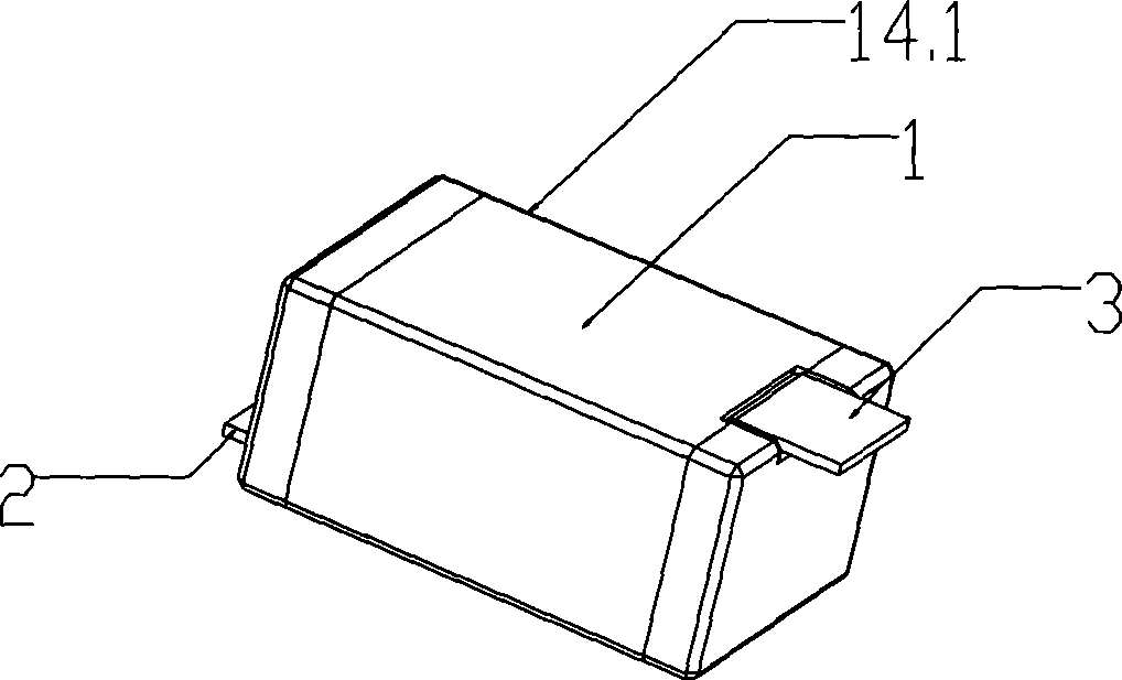
[0075] see figure 1

[0076] figure 1 It is a perspective view of the short circuit protection device in the present invention. exist figure 1 Among them, the varistor body 14 with the short-circuit protection device 14.1 includes an insulator matrix body 1, and the electrodes 2 and 3 protrude from both ends of the insulator matrix body 1 of the short-circuit protection device 14.1, and the electrode 3 has The function of heat transfer, conduction and fixed short-circuit protection device 14.1, the electrode 2 is used to be connected with the lead-out pin 13 of the piezoresistor body 14 (such as Figure 4 shown).
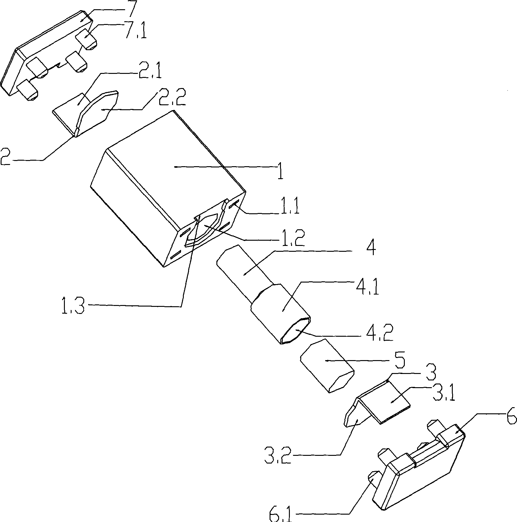
[0077] see figure 2

[0078] figure 2 It is an assembly diagram of components of the short-circuit protection device in the present invention. exist figure 2 Among them, the insulator matrix body 1 and the i...


PUM


Abstract

A type of piezoresistance equipped with new type short protecting device, the piezoresistance is parallel connected with the new type short protecting device, the short protecting device is hot melt body which at least includes two parts, thereinto at least one part is hollow part, the other part is solid part; the short protecting device includes insulator base noumenon, thermal deformation material subassembly, electrode, insulator outer cover; the insulator base includes through hole which is used to mount thermal deformation material subassembly and several mounting holes which is used tomount the insulator outer cover; the insulator base is equipped with fixed metal electrode; the thermal deformation material subassembly includes little conduit and big cannula which is set with thermal deformation material, temperature controlling weldable fusible alloy which is used to fill in the cavity of big cannula, the insulator outer cover includes protruding foot which matches with number and diameter of mounting hole and groove which spreads the insulator base noumenon. The invention is close mode protection, the structure is simple, and the safety is well, energy-saving, consummation is decreased, environmental protection, the operation is stable, and it is easy to detect; The efficiency is high, cost is low, and the service life is long.

Description

technical field [0001] The invention relates to an electrical component, in particular to a piezoresistor with a short-circuit protection device. Background technique [0002] With the rapid development of modern electronic and electrical technology, more and more electronic and electrical equipment (such as: electronic equipment, network equipment, household appliances, electricity, electrical, medical, computer integrated circuits, etc.) are widely used in various fields, and At the same time, these electronic and electrical equipment are all subjected to lightning surge natural disasters and various electromagnetic interference surge currents and surge voltages without exception, causing these devices to fail to work normally, and in severe cases, they will catch fire, burn, explode, etc. [0003] An effective way to solve the above problems is to connect one or more groups of MOV zinc oxide varistors in parallel at the input terminals of these devices to absorb various ...

Claims


Application Information

Patent Timeline
Patent Type & Authority Patents(China)
IPC IPC(8): H01C7/10H01C7/13
Inventor 甘立刚
Owner 甘立刚
Why Eureka
Try Eureka