Combined catforming of high-production low carbon alkene
A catalytic conversion method and technology of low-carbon olefins, applied in the direction of hydrocarbon cracking, chemical recovery, organic chemistry, etc., can solve the problems of longer residence time, intensified thermal cracking, and increased dry gas yield, so as to achieve easy desorption, The effect of increasing the ratio of agent to oil and increasing the yield
- Summary
- Abstract
- Description
- Claims
- Application Information
AI Technical Summary
Problems solved by technology
Method used
Image

Examples
Embodiment approach 1
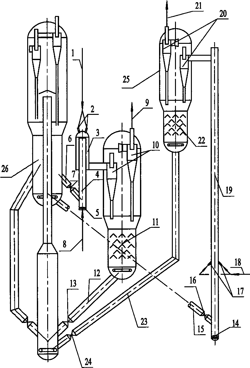
[0032] Such as figure 1 As shown, the first regenerated catalyst at about 720°C enters the pre-elevating section 4 of the down tube reactor through the transfer line 6 and the flow control valve 7, and the pre-elevating medium from the pipeline 8 enters the pre-elevating section 4 through the distributor 5. The catalyst in the pre-lift section 4 is lifted to the inlet of the down tube reactor 3. The pre-lifting medium can be water vapor, dry gas from or outside the device, C4 component in cracked gas, or a mixture of these gases. The preheated heavy oil feedstock is atomized by atomizing water vapor through the pipeline 1 and nozzle 2 and then injected into the down tube reactor 3 to contact and react with the hot catalyst from the catalyst pre-lifting section 4. The reaction temperature is 500-650°C, preferably 520-620°C; the reaction pressure is 1.5-5×10 5 Pa, preferably 1.8-4×10 5 Pa; reaction time is 0.1-1.5 seconds, preferably 0.15-1 second; the weight flow ratio of catal...
Embodiment approach 2
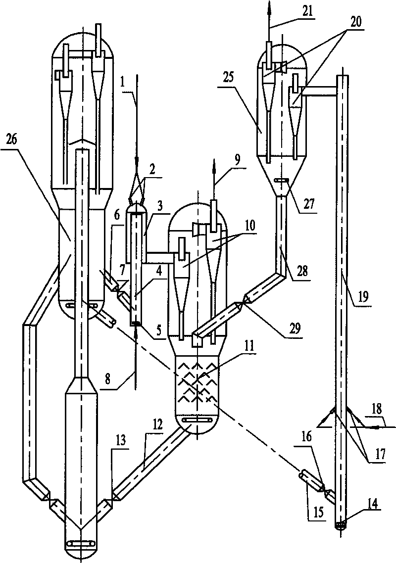
[0035] figure 2 Shown is the second embodiment of the present invention. The difference between this embodiment and the first embodiment is that the catalyst separated by the gas-solid separation device 20 at the outlet of the riser does not enter the catalyst regeneration system directly after being pre-stripped with steam injected through the distribution pipe 27 at the lower part of the settler 25 , It enters the stripper 11 below the gas-solid separation system of the down tube reactor through the transfer line 28 and the catalyst flow control valve 29, and mixes with the catalyst collected by the gas-solid separation system of the down tube reactor, and then enters the stripper together. 11 receives steam stripping, and then enters the regenerator through the transfer line 12 and the catalyst flow control valve 13 to be burnt and regenerated, and then returns to the reaction system for recycling. Because the reaction temperature of the riser is higher than that of the dow...
Embodiment approach
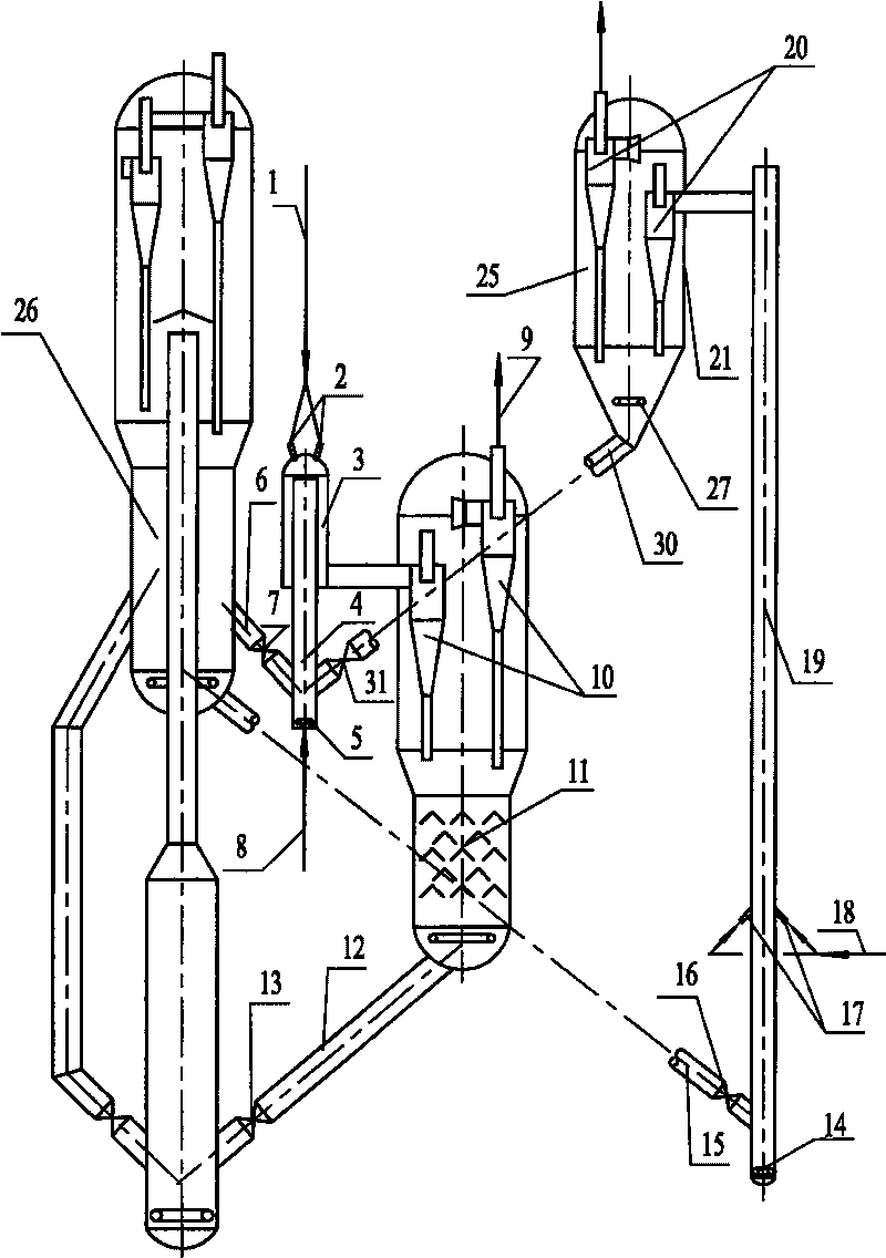
[0037] image 3 Shown is the third embodiment of the present invention. The difference between this embodiment and the first embodiment is that the catalyst separated by the gas-solid separation device 20 at the outlet of the riser is injected into the lower part of the settler 25 through the distribution pipe 27 After the steam is pre-stripped, it does not directly enter the catalyst regeneration system, but enters the catalyst pre-lift section 4 of the down tube reactor through the pipeline 30 and the catalyst flow control valve 31. In the pre-lift section 4, the first regenerated catalyst passes through the reactor. After mixing for less than two seconds, it comes into contact with the feed oil injected into the down tube reactor. Because the raw material for the riser reaction is lighter and the reaction temperature is relatively high, the catalyst after the reaction has less carbon deposits and still has a relatively high Activity and temperature. The introduction of this ...
PUM
 Abstract
Description
Claims
Application Information
 - R&D
- Intellectual Property
- Life Sciences
- Materials
- Tech Scout
- Unparalleled Data Quality
- Higher Quality Content
- 60% Fewer Hallucinations
Browse by: Latest US Patents, China's latest patents, Technical Efficacy Thesaurus, Application Domain, Technology Topic, Popular Technical Reports.
© 2025 PatSnap. All rights reserved.Legal|Privacy policy|Modern Slavery Act Transparency Statement|Sitemap|About US| Contact US: help@patsnap.com