Mixed gradual conversion field of proton exchange membrane fuel cell

A proton exchange membrane and fuel cell technology, which is applied to fuel cells, fuel cell parts, battery electrodes, etc., can solve the problems of uneven distribution of fuel reactions, and the problem of easy liquefaction of water at the fuel outlet. Achieve the effect of improving fluid inhomogeneity, compact structure and easy processing

Inactive Publication Date: 2007-10-03
UNIV OF SCI & TECH BEIJING
View PDF1 Cites 23 Cited by
  • Summary
  • Abstract
  • Description
  • Claims
  • Application Information

AI Technical Summary

Problems solved by technology

The above flow fields solve the problem of uneven distribution of fuel reactions in fuel cells t...

Method used


Image

  • Mixed gradual conversion field of proton exchange membrane fuel cell
  • Mixed gradual conversion field of proton exchange membrane fuel cell
  • Mixed gradual conversion field of proton exchange membrane fuel cell

Examples


Embodiment 1

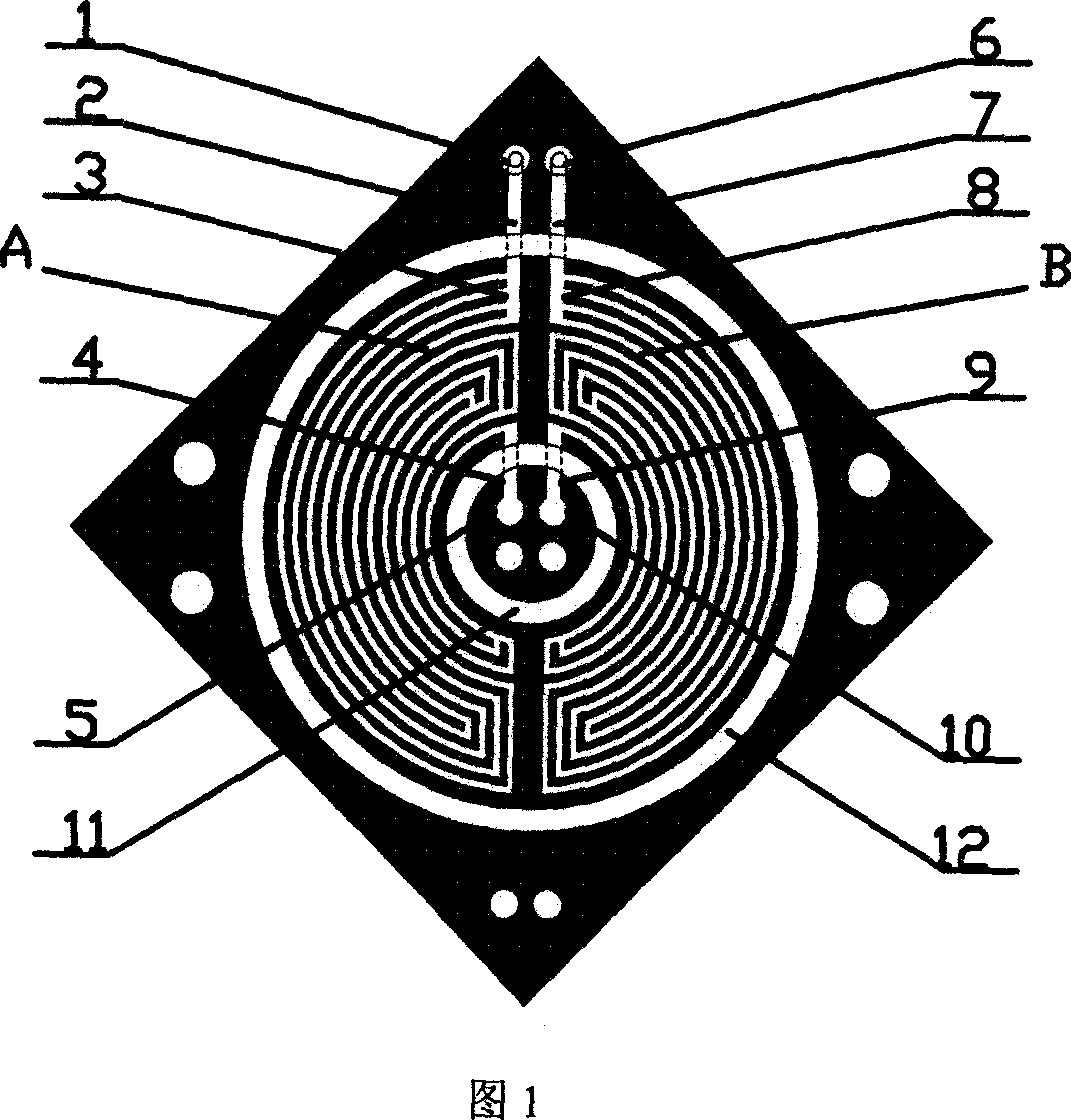
[0033] The flow field involves two pairs of fuel inlets and outlets. A stainless steel plate with a substrate size of 90 mm x 90 mm x 3 mm (length x width x thickness) was machined. As shown in Figure 1, taking the left half as an example, the fuel enters from the inlet 1, the diameter of the inlet through hole is 4mm, flows into the distribution groove 3 through the diversion groove 2 under the outer sealing groove, and the diversion groove 2 The cross section is a rectangular opening, and the cross section (width × height) is 2 mm × 1 mm. The distribution groove 3 evenly distributes the reacted fuel to the parallel 4 passages of the second level. The cross section of the distribution groove 3 is a rectangular opening, and its ( Length x width x depth) 16mm x 2mm x 1mm. The distribution groove is 0.5mm deeper than the flow field groove, so as to fully divert the fuel in the diversion groove 2 .

[0034] The regions of grooves A and B are respectively the left and right half...

Embodiment 2

[0037] The shape and structure of the multi-channel gradient flow field are basically the same as those in Example 1. The width of the grooves and ridges in the reaction regions A and B of the mixed flow field is 0.5 mm, the depth of the grooves is 0.4 mm, and the sealing grooves 11 and 12 are The width is 0.2mm, and the depth of the sealing groove is 0.1mm. The difference is that the fuel inlet 6, the diversion groove 7, the distribution groove 8, the diversion groove 9, the fuel outlet 10, and the flow field areas B and 1, 2 , 3, 4, 5 and flow field area A are symmetrical about the center point. That is, it is anti-symmetrical to the right part of the embodiment in the horizontal direction. As shown in Figure 7.

Embodiment 3

[0039] The groove cross-sectional size of the multi-channel gradient flow field is the same as that of Example 1, the width of the groove and the width of the ridge in the mixed flow field reaction area A and B are 1.5mm, and the groove depth is 1.0mm. The difference is that the flow field The whole only involves a pair of fuel inlet and outlet, as shown in Figure 8.

[0040] The invention improves the non-uniform distribution of the multi-channel serpentine flow field reaction fuel end, avoids the phenomenon of temperature drop at the outlet of the traditional structure, reduces the heat loss at the edge of the battery, and avoids the phenomenon of water flooding at the outlet.


PUM


Abstract

A mixed and gradually varied flow field of proton exchange film fuel cell consists of slots at reaction region of mixed flow field, flow guiding slots at inlet and outlet, sealing slots and distribution slots for connecting flow guiding slots to slots at reaction region of mixed flow field. It is featured as setting slots at reaction region of mixed flow field to be multilayer grade slots in arc form and setting center of circle at sealing slots to be with the same central point as center of circle on slots at reaction region of mixed flow field.

Description

technical field [0001] The invention belongs to the flow field of a fuel cell, in particular to a flow field structure of a proton exchange membrane fuel cell. Background technique [0002] A fuel cell is a power generation device that can efficiently convert fuel and oxidant directly into electrical energy through electrode reactions. Proton exchange membrane fuel cell (PEMFC) is a fuel cell with perfluorosulfonic acid ion exchange membrane as electrolyte, hydrogen or methanol as fuel, and air or oxygen as oxidant. The core of PEMFC is membrane MEA and bipolar plate. Membrane MEA is the place of electrochemical reaction. The bipolar plate provides gas distribution and current collection. In order to complete the two tasks of gas distribution and current collection, the bipolar plate usually needs to have good electrical conductivity, good thermal conductivity, resistance to fuel and Oxidant penetration and corrosion resistance in electrochemical environments, etc. The fl...

Claims


Application Information

Patent Timeline
IPC IPC(8): H01M8/02H01M4/86H01M8/0258H01M8/026H01M8/1016
CPCY02E60/50
Inventor 王新东马利军林才顺
Owner UNIV OF SCI & TECH BEIJING
Why Eureka
Try Eureka