Device for photochemical degradating pollution gas

A photochemical and gas technology, applied in chemical instruments and methods, chemical/physical/physicochemical processes of energy application, separation of dispersed particles, etc., can solve problems such as difficult to handle adsorbates, complex equipment structure, high operating costs, etc., to achieve Avoiding economic burden, convenient manufacturing and installation, and improved purification effect

Inactive Publication Date: 2007-10-17
FUJIAN NEWLAND ENTECH CO LTD
View PDF0 Cites 10 Cited by
  • Summary
  • Abstract
  • Description
  • Claims
  • Application Information

AI Technical Summary

Problems solved by technology

But its disadvantages are large equipment investment and high operating costs, high cost; complex equipment structure; easy to spontaneous combustion, poor safety
[0008] To sum up, the existing polluting gas degradation methods or equipment have the disadvantages of high cost, refractory adsorbate, secondary pollution or spontaneous combustion, and poor safety.

Method used


Image

  • Device for photochemical degradating pollution gas
  • Device for photochemical degradating pollution gas

Examples


Embodiment Construction

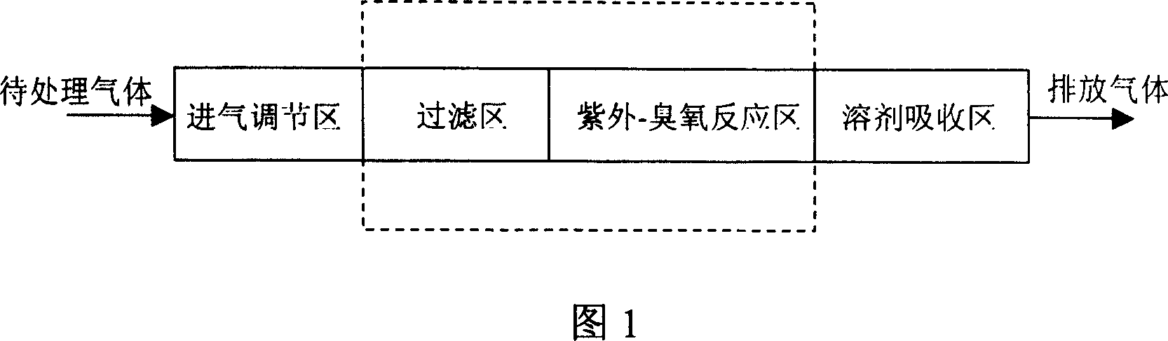
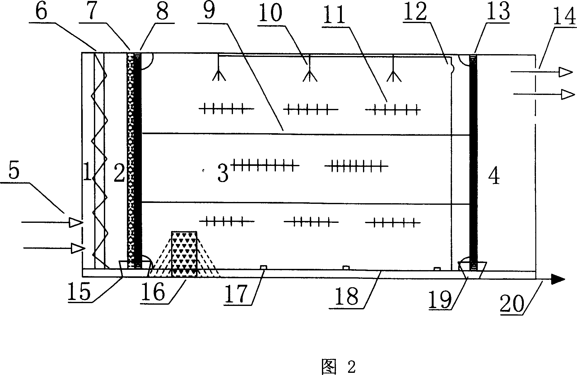
[0024] The reactor main body of the photochemical degradation polluting gas device shown in Figure 2 is a fixed building with a prism-shaped inner cavity constructed of concrete. The interior of the reactor main body is a whole, which is divided into air intake adjustment area 1 according to its function. , filter area 2, ultraviolet-ozone reaction area 3, solvent absorption area 4 four functional areas, filter area 2 and ultraviolet-ozone reaction area 3 are separated by primary filter layer 7 and secondary filter layer 8, described The ultraviolet lamp group 11 is located in the ultraviolet-ozone reaction zone 3 and is supported by a support frame 13. Each ultraviolet lamp group contains at least one ultraviolet lamp tube. When the equipment is running, there is ozone gas in the ultraviolet-ozone reaction zone 3, and the air inlet 5 and The gas outlets 14 are respectively located at the front end of the intake adjustment area 1 and the rear end of the solvent absorption area ...


PUM


Abstract

The invention provides a device for optics degradating dusty gas, comprising a container used as a reactor characterized in that: the reactor is composed of an air inlet control zone, a filter zone, a UV-ozone reacting zone and a solution absorbing zone, wherein they need not be connected by conduit, the UV-ozone reacting zone is at least mounted with a ultraviolet light cluster each comprising at least one ultraviolet light tube, there is ozone in the UV-ozone reacting zone when the device runs, and the tail gas is completely purified by solution absorbing unit to discharge from the exhaust port after air inlet controlled. The invention can be used for the treatment of the dusty gas like 'three-benzene' discharged by the plant of shoes and furnishings, for the treatment of the exhaust gas with fetid smell discharged by effluent treatment plant, tannery, culturing plant and pharmaceutical factory, and also for the pollution gas discharged by other factories.

Description

Technical field: [0001] The invention belongs to the technical field of using photochemical technology to degrade polluting gases, in particular to a device for treating polluting gases such as triphenyl gas, volatile organic compound gas (VOC) and malodorous gas by using ultraviolet rays and ozone. Background technique: [0002] With the development of industry and agriculture, the direct discharge of polluting gases produced in the production process has caused great pollution to the environment of our country. The polluting gases referred to here refer to gases containing volatile organic compounds (VOC) or other harmful inorganic gases. Such as hydrogen sulfide, ammonia and various odorous gases. Especially the serious fact that the polluting gases produced in industrial and agricultural production such as chemical industry, paint, printing, shoemaking, pharmaceutical factories, and farms cause serious air pollution and endanger human health has attracted more and more a...

Claims


Application Information

Patent Timeline
Patent Type & Authority Applications(China)
IPC IPC(8): B01D53/76B01J19/12
Inventor 陈健朱国营姚向阳
Owner FUJIAN NEWLAND ENTECH CO LTD
Why Eureka
Try Eureka