Hydraulic oil pump
An oil well pump and hydraulic technology, applied in the field of hydraulic oil well pumps, can solve the problems of reduced efficiency of the whole machine, oil pipe wear and leakage, and difficulty in reaching the working life of the dynamic sealing surface.
- Summary
- Abstract
- Description
- Claims
- Application Information
AI Technical Summary
Problems solved by technology
Method used
Image
Examples
Embodiment 1
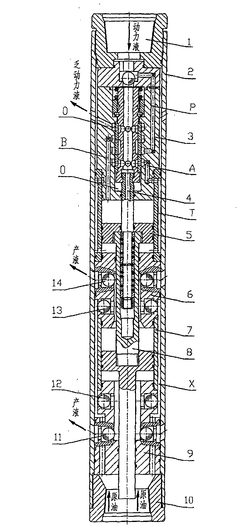
[0087] Embodiment 1: see attached figure 1 . In the first circuit: a single-drive single-pump hydraulic oil pump with a primary drive cylinder 5 and a liquid discharge cylinder 7, including an upper joint 1, a pump casing 2, a reversing valve 3, a control mechanism 4, and a drive cylinder 5 , The upper end discharges the suction valve assembly 6, the liquid discharge cylinder 7, the hollow piston rod 8, the lower end discharges the suction valve assembly 9 and the lower joint 10.
[0088] The outer diameter of the hydraulic oil well pump is determined as φ 114 mm, the drive cylinder 5 bore is φ 70 mm, the drain cylinder 7 is φ 75 mm, and the working stroke of the two cylinders is 700 mm, then the total length of the pump is about 3600 mm.
[0089] The lower end of the upper joint 1 is threadedly connected with the pump casing 2 and sealed; the center hole of the upper joint 1 communicates with the "P" port of the reversing valve 3, and there is a sealing ring between the lowe...
Embodiment 2
[0098] Embodiment 2: see attached figure 2 . In the first circuit: a hydraulic oil pump with a double-drive single-pump structure with a drive cylinder 5, a second-stage drive cylinder 5' and a liquid discharge cylinder 7, the drive cylinder 5 and the second-stage drive cylinder 5' are shared A cylinder, two pistons are arranged in the cylinder of the driving cylinder, and the dividing plate 17 between the two pistons is connected with the inner diameter of the cylinder by a key, and sealing rings are arranged on both sides of the key.
[0099] Including upper joint 1, pump casing 2, reversing valve 3, control mechanism 4, drive cylinder 5, second stage drive cylinder 5', spacer 17, upper end discharge and suction valve assembly 6, liquid discharge cylinder 7, hollow piston The rod 8, the lower end discharges the suction valve assembly 9 and the lower joint 10.
[0100] The outer diameter of the hydraulic oil well pump is set at φ114 mm, the bore diameter of the drive cylin...
Embodiment 3
[0106] Embodiment 3: see attached image 3 . In the first circuit: a single-drive double-pump structure hydraulic oil well pump for the primary drive cylinder 5, the liquid discharge cylinder 7 and the lower end liquid discharge cylinder 7'.
[0107] Including upper joint 1, pump casing 2, reversing valve 3, control mechanism 4, drive cylinder 5, upper discharge and suction valve assembly 6, liquid discharge cylinder 7, lower discharge cylinder 7', middle and lower discharge and suction valve assembly Into 15, middle and lower discharge suction valve assembly 16, hollow piston rod 8, lower end discharge suction valve assembly 9 and lower joint 10.
[0108] The outer diameter of the hydraulic oil pump is set at φ114 mm, the cylinder diameter of the drive cylinder 5 is φ70 mm, the liquid discharge cylinder 7 and the lower end liquid discharge cylinder 7′ are φ75 mm, and the working strokes of the three cylinders are all 700 mm, then the pump’s The total length is about 4160 mm...
PUM
 Abstract
Description
Claims
Application Information
 - R&D
- Intellectual Property
- Life Sciences
- Materials
- Tech Scout
- Unparalleled Data Quality
- Higher Quality Content
- 60% Fewer Hallucinations
Browse by: Latest US Patents, China's latest patents, Technical Efficacy Thesaurus, Application Domain, Technology Topic, Popular Technical Reports.
© 2025 PatSnap. All rights reserved.Legal|Privacy policy|Modern Slavery Act Transparency Statement|Sitemap|About US| Contact US: help@patsnap.com


