Hydraulic oil pump

An oil pump and hydraulic technology, which is applied in the field of hydraulic oil pump, can solve the problems such as the decline of the efficiency of the whole machine, the inability to eliminate, and the inability to adapt to directional wells, horizontal wells and oil production.

Active Publication Date: 2007-10-17
ZHONGCHAO LIANHE ENERGY SCI & TECH BEIJING CO LTD
View PDF0 Cites 19 Cited by
  • Summary
  • Abstract
  • Description
  • Claims
  • Application Information

AI Technical Summary

Problems solved by technology

Rod pumps driven by conventional beam pumping units cannot adapt to directional wells, horizontal wells, and oil production in later stages of oil well production.
The efficiency of the conventional pumping unit drops to less than 20% due to the friction between the sucker rod and the tubing in the production of inclined wells; what is more serious is that the sucker rod breaks off or the tubing wears and leaks due to the eccentric wear of the sucker rod, resulting in Check the pump frequently
Coupled with the inability of rod well pumps to play a role in deep wells, rod well pumps in the field of oil production are facing serious challenges
Rodless oil production pumps, such as electric submersible pumps and jet pumps, have their own inherent defects that cannot be eliminated, making it difficult to play a leading role in oil production in inclined wells
[0003] Originally, the hydraulic oil well pump that realizes reversing in the well is the best technical route for the development of rodless oil well pumps. However, the design scheme of the hydraulic piston pump imported from the United States in the 1980s has serious deficiencies, and the flow resistance of the pipeline in the pump is as high as 3.8-5.3 Mpa, which is equivalent to the back-and-forth flow resistance in the liquid pipe when the depth of the lower pump is 2000-3000m; in addition, the reversing valve and the control mechanism move synchronously with the power cylinder. The fatal flaw of this control method is: no matter how low the movement speed of the power cylinder is, No matter how wear-resistant and corrosion-resistant the dynamic seal of the reversing valve is, the short dynamic sealing surface is difficult to achieve the working life of several months of continuous operation.
Although this rodless hydraulic oil pump has its advantages, its disadvantages are also obvious: 1. It can only be controlled by a single well, which is inconvenient to manage; 2. The configuration equipment is complicated and the operation is troublesome; High cost; 4. It is difficult to guarantee the reliability of hydraulic components in the field environment; 5. The downhole signal transmission lags behind, and the invalid stroke of the pump increases. Therefore, the use prospect of this rodless hydraulic oil well pump is still not optimistic.

Method used


Image

  • Hydraulic oil pump
  • Hydraulic oil pump
  • Hydraulic oil pump

Examples


Embodiment 1

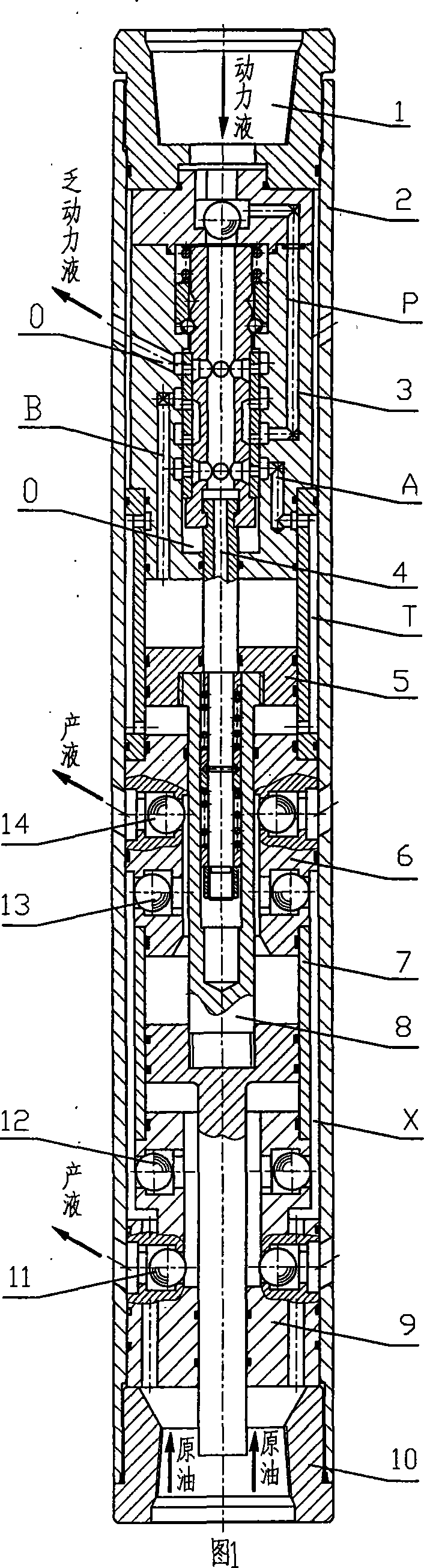
[0087] Embodiment 1: refer to accompanying drawing 1. In the first circuit: a single-drive single-pump hydraulic oil well pump with a primary drive cylinder 5 and a liquid discharge cylinder 7, including an upper joint 1, a pump casing 2, a reversing valve 3, a control mechanism 4, and a drive cylinder 5 , Discharge and suction valve assembly 6, liquid discharge cylinder 7, hollow piston rod 8, discharge and suction valve assembly 9 and lower joint 10.

[0088] The outer diameter of the hydraulic oil well pump is determined as φ 114 millimeters, the drive cylinder 5 bore is φ 70 millimeters, the drain cylinder 7 is φ 75 millimeters, and the working stroke of the two cylinders is 700 millimeters, then the total length of the pump is about 3600 millimeters.

[0089] The lower end of the upper joint 1 is threadedly connected with the pump casing 2 and sealed; the center hole of the upper joint 1 communicates with the "P" port of the reversing valve 3, and there is a sealing ring ...

Embodiment 2

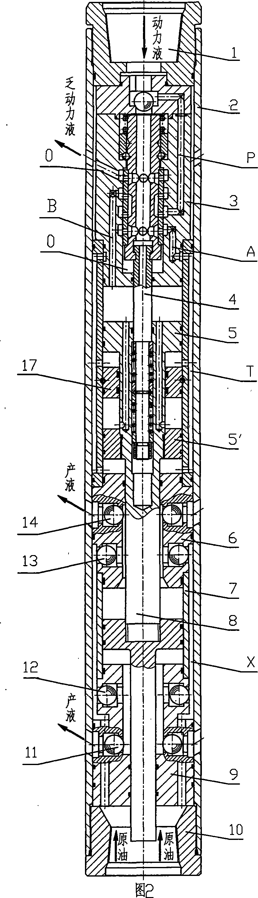
[0098] Embodiment 2: refer to accompanying drawing 2. In the first circuit: a hydraulic oil pump with a double-drive single-pump structure of two-stage drive cylinders 5, 5' and a liquid discharge cylinder 7, the two-stage drive cylinders 5, 5' share a cylinder barrel, and the drive cylinder There are two pistons in the cylinder, and the dividing plate 17 between the two pistons is connected with the inner diameter of the cylinder by a key, and sealing rings are arranged on both sides of the key.

[0099] Including upper joint 1, pump casing 2, reversing valve 3, control mechanism 4, drive cylinder 5, 5', spacer 17, discharge suction valve assembly 6, liquid discharge cylinder 7, hollow piston rod 8, discharge suction valve Seoul assembly 9 and lower joint 10.

[0100] The outer diameter of the hydraulic oil well pump is set at φ114 mm, the bore of the driving cylinder 5 and 5′ is φ70 mm, the discharge cylinder 7 is φ75 mm, and the working strokes of the three cylinders are a...

Embodiment 3

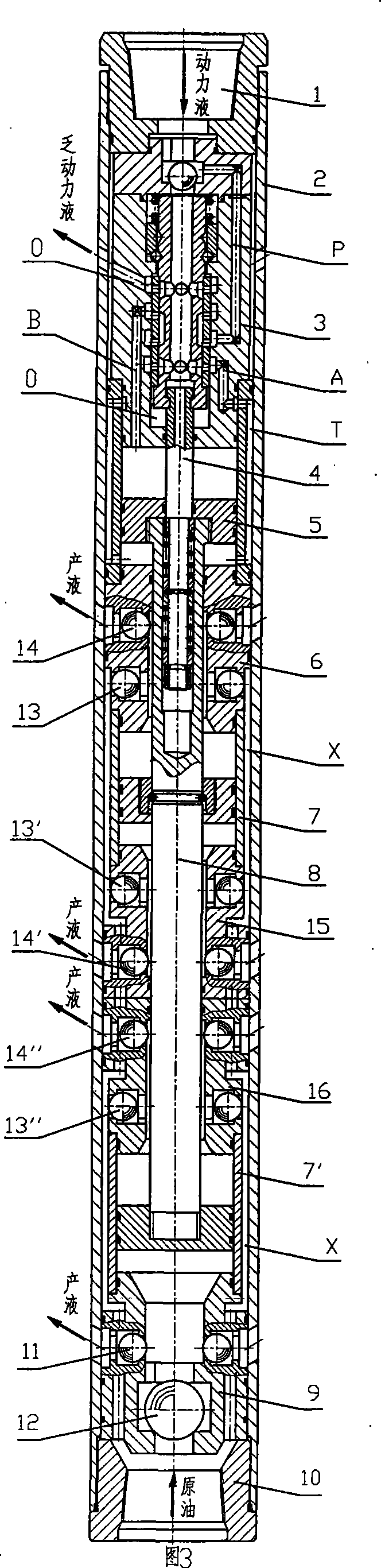
[0106] Embodiment 3: refer to accompanying drawing 3. In the first circuit: a single-drive double-pump hydraulic oil pump with a primary drive cylinder 5 and two liquid discharge cylinders 7, 7'.

[0107] Including upper joint 1, pump casing 2, reversing valve 3, control mechanism 4, drive cylinder 5, discharge suction valve assembly 6, liquid discharge cylinder 7, 7', discharge suction valve assembly 15, 16, hollow piston Rod 8, discharge suction valve assembly 9 and lower joint 10.

[0108] The outer diameter of the hydraulic oil well pump is set at φ114 mm, the cylinder diameter of drive cylinder 5 is φ70 mm, the discharge cylinder 7, 7′ is φ75 mm, and the working strokes of the three cylinders are all 700 mm, then the total length of the pump is 4160 mm about.

[0109] Reversing valve 3, control mechanism 4, discharge suction valve assembly 6,9 are identical with embodiment 1, and wherein suction valve 12 also can be placed in the middle of valve body.

[0110] The "O" ...


PUM


Abstract

A hydraulic oil pump realizes automatic switch by depending the oil well liquid provided by ground pump station as power liquid. The pump includes an upper joint, a pump housing, a switch valve, a control mechanism, a drive cylinder, an upper discharge suck valve assembly, a hollow piston rod, a liquid discharging cylinder, a lower discharge suck valve assembly and a lower joint. Two different opening loops can be adopted according to different well conditions; each loop has four implementing schemes. The effect is that: the pump thoroughly changes the control mode that the switch valve and drive cylinder moves synchronously in conventional water power piston pump, the switch valve is at non-friction state in most time, and the sealing surface will not bearing erosion during switch process. Therefore, the pump has strong reliability and low requirement for power liquid quality, and has a power consumption which is only 25-30% of existing oil pump; thereby it is perfect equipment for oil extraction from inclined well, deep well and dense oil well.

Description

Technical field: [0001] The invention relates to the technical field of petroleum rodless oil production, in particular to a hydraulic oil well pump which relies on a surface pump station to provide power fluid and realizes automatic reversing underground. technical background [0002] Conventional beam pumping units have low efficiency, but they have always occupied a dominant position in the field of oil extraction for many years because of their reliable performance and convenient management. With the rapid development of directional wells and horizontal wells technology, and oilfields entering the late stage of oil production, the viscosity of crude oil increases, water cut increases, sand production increases, and the liquid level of oil wells decreases, making oil recovery more difficult year by year. Rod pumps driven by conventional beam pumping units cannot adapt to directional wells, horizontal wells, and oil wells in the later stage of oil production. The efficien...

Claims


Application Information

Patent Timeline
Patent Type & Authority Applications(China)
IPC IPC(8): F04B47/08E21B43/00
CPCE21B43/129F04B47/08
Inventor 李洪敏
Owner ZHONGCHAO LIANHE ENERGY SCI & TECH BEIJING CO LTD
Why Eureka
Try Eureka